

Model trains - Passenger cars lighting
The pictures can be clicked on to see them in the original format in a new tab.
You, as a model trains enthousiast might be familiar with the lights in your passenger cars flickering.
If there was a way to add lighting for your cars anyway.
When I was young, very young (might have been 13, no excuse), I already made interior lighting in my passenger cars.
A bit crude and certainly not perfect. Here is an example from my old collection.
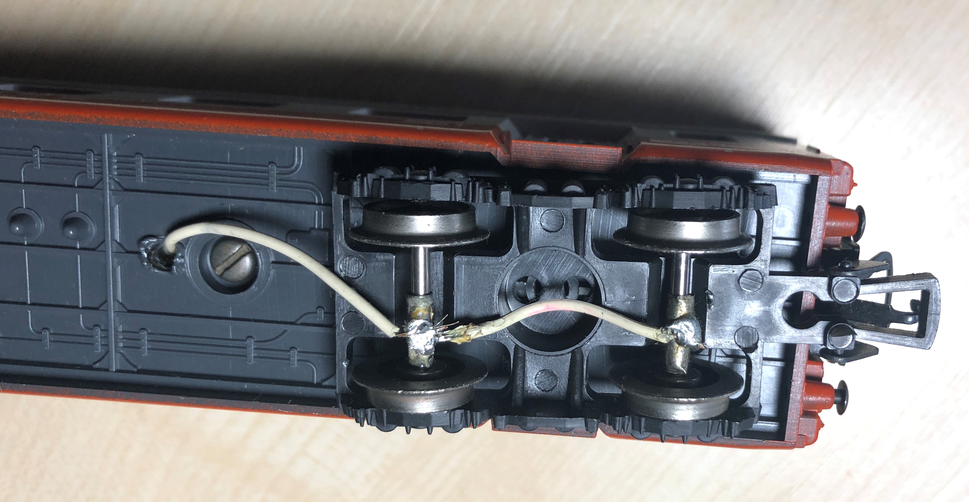
The solcering was more a kind of pasting. I used a piece of small copper pipe
The copper pipe was a smart idea, I thought. Most of the times it touched the axes. One disadvantage was I had to remove one wheel from the axel.
Almost 50 years further dow the line I picked up model trains again, and hopefully I know better now. Or at least learned from the past.
I used two methods to build flicker free lighting in my carriages.
First I build lighting in my Lima DB TEE colored carriages.
Second I used my NS plan E carriages.
Jump directly to
German DB carriages
Ducth NS carriages
It all starts with the compnents.
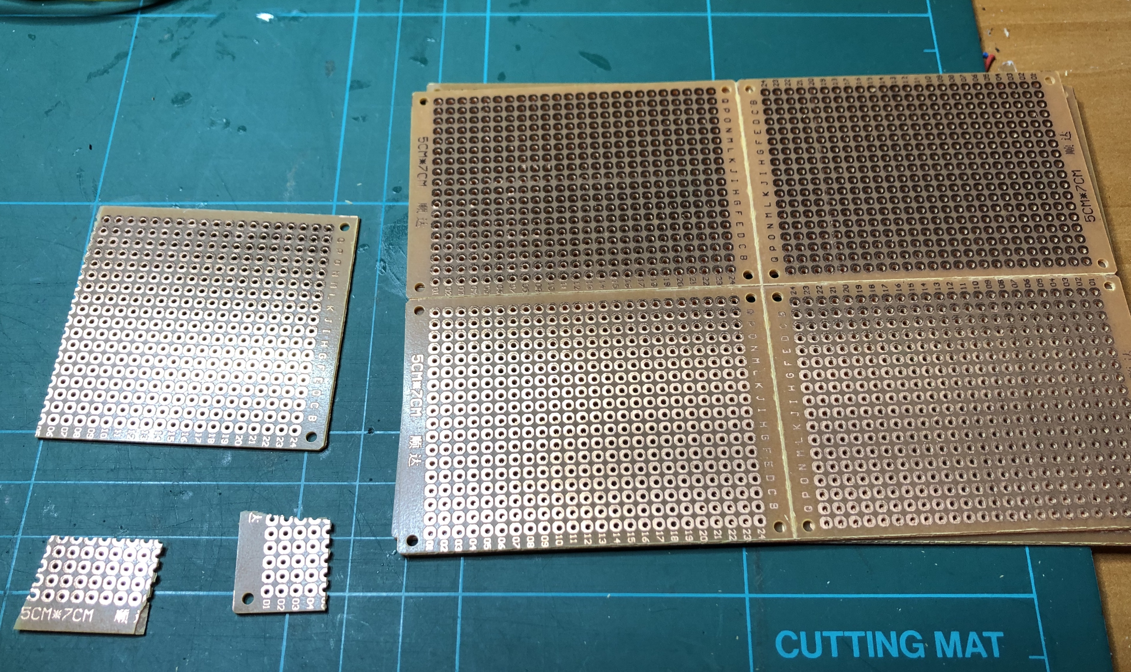
You need something to mount the components on. I used cheap pertinax board.
 |
 |
It come in big sizes. just cut off the size you need. The right picture shows you do not need much
The small piece is about 1.5 by 1 cm. After all, it needs to fit the carriage.
The electronics I used:
Piece of pertinax board
SMD bridge rectifier
SMD 7806 regulator
Capacitor 10uF, 16 volt or higher
Capacitor 220uF to 1000uF, 16 volt
12 volt LED strip yellow
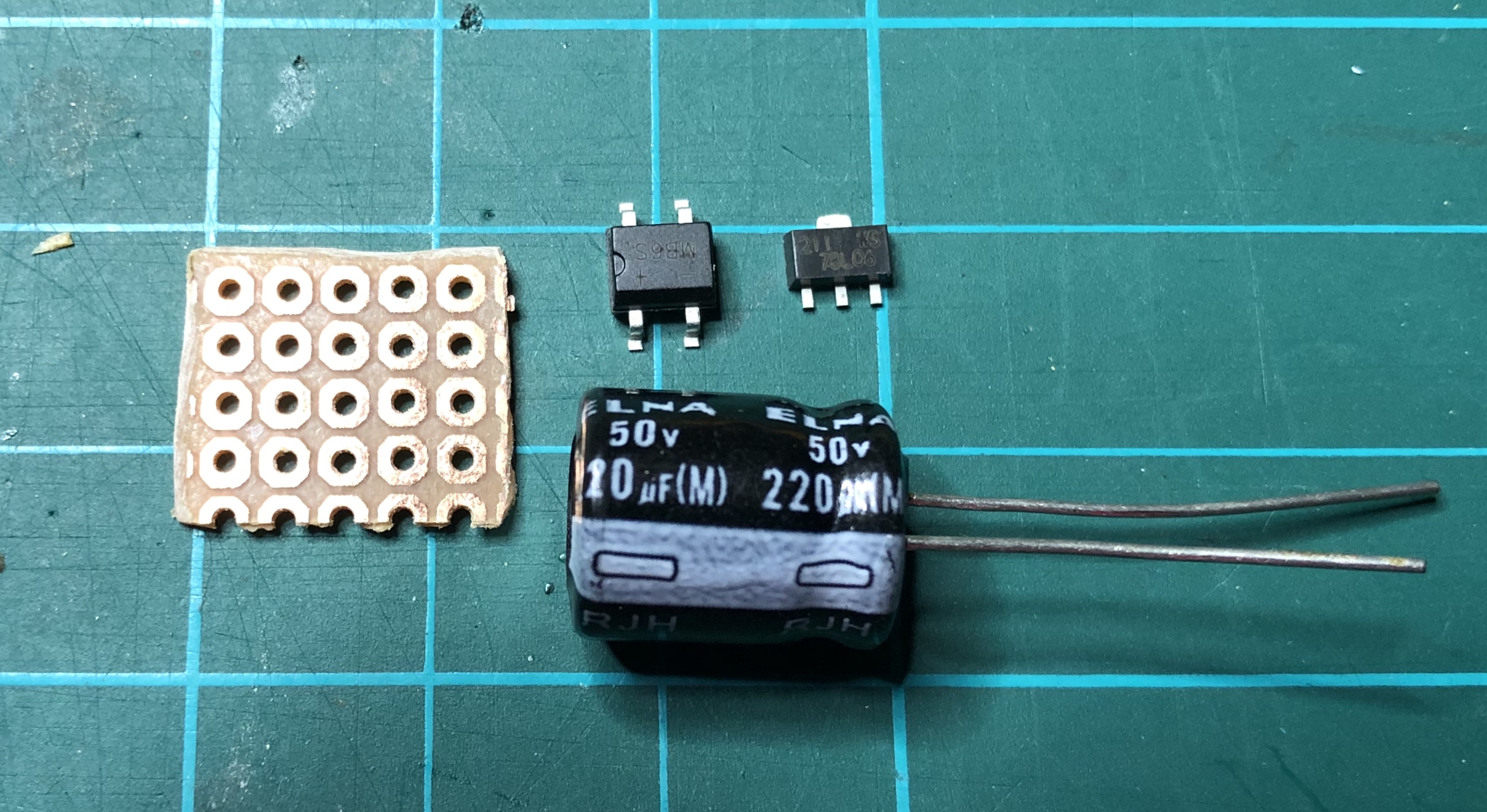
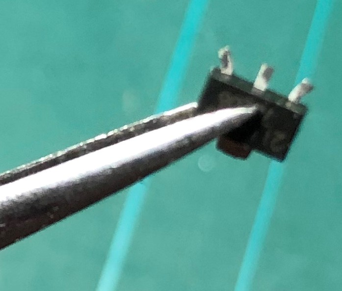
Below you see "all" components together. Prepare the bridge rectifier and regulator.
The rectifier has slidely bend connectors. With some pliers straighten these, so they fit in the holes on the board.
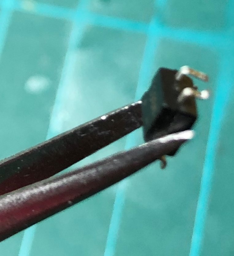
The regulator outer connectors need to be bend out a bit, see picture. Caution, they are very fragile and will come off when done with force.
|
|
 |
 |
Now the arrangement on the board.
These small components are difficult to solder. Preferably use a temperature controlled soldering iron with a fine tip.
Some people put a small dot of glue under the components so that they stay in place while soldering.
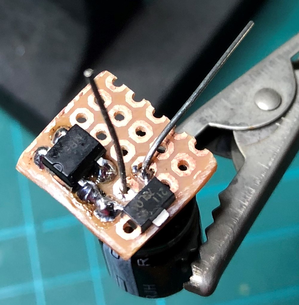
Start soldering the bridge rectifier. Note: pay attention to the pin layout. The pins with the ~~ should be towards the edge of the board.
Then the regulator. Don't solder the middle leg of the regulator yet.
Make a solder connection between the two left legs of the regulator and rectifier.
Mount the capacitor from the other side of the board. Pay attention to polarity. The white stripe on the capacitor is the minus side.
Now solder the middle leg of the regulator, the minus leg of the capacitor and the right leg of the rectifier together. Caution with the solder, you will have a short circuit easily.
 |
 |
 |
 |
The four described stages in pictures
I kept a millimeter space between the capacitor and the board. It is used to fix the board into the interior of the carriage.
Depending on the carriage and space you have, you can also mount the capacitor directly on the board and glue the board into the carriage.
 |
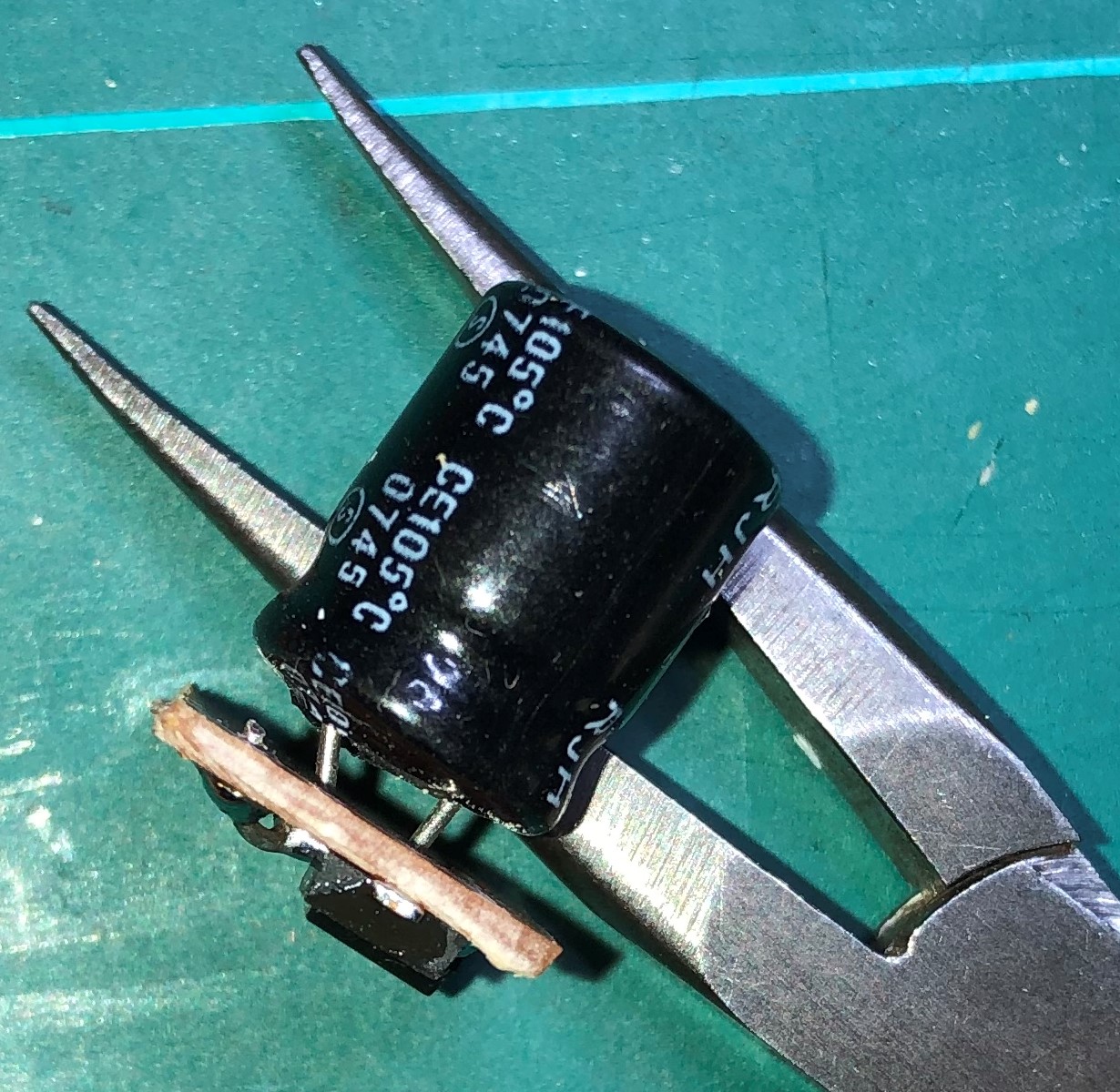 |
The end result. From top and side view
Solder some wires to the board for testing before you mount it in the carriage.
When you look closely, one can see this board won't work. I forgot to solder the right leg of the rectifier and the middle leg of the regulator together.
After fixing the solder problem I put the transformer at half "speed" and measured the voltage coming from the board. Obviously,becuase I used a 6 volt regulator, it is around 6 volts.
 |
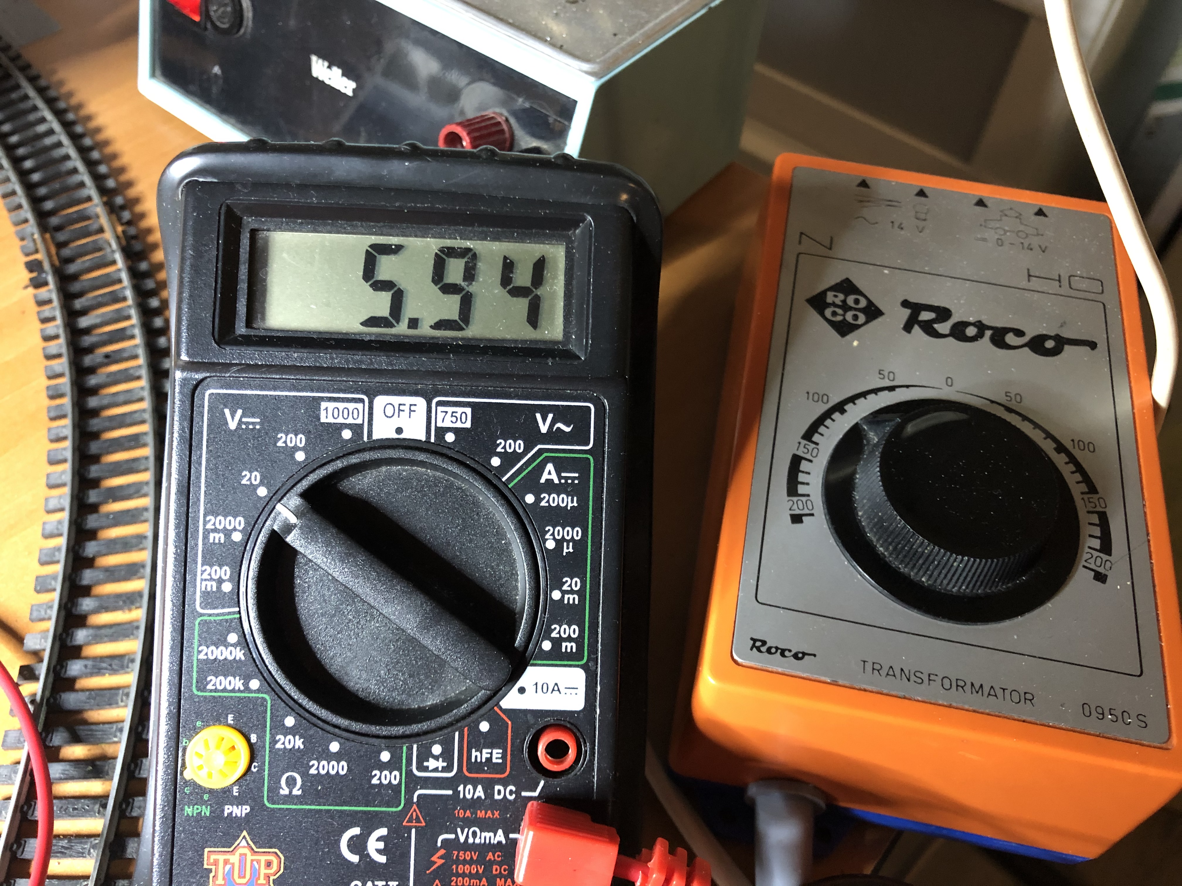 |
Faulty board and regulated result
As proof the rectifier and regulator work fine I turned up the voltage ("speed") on the transformer and switched polarity.
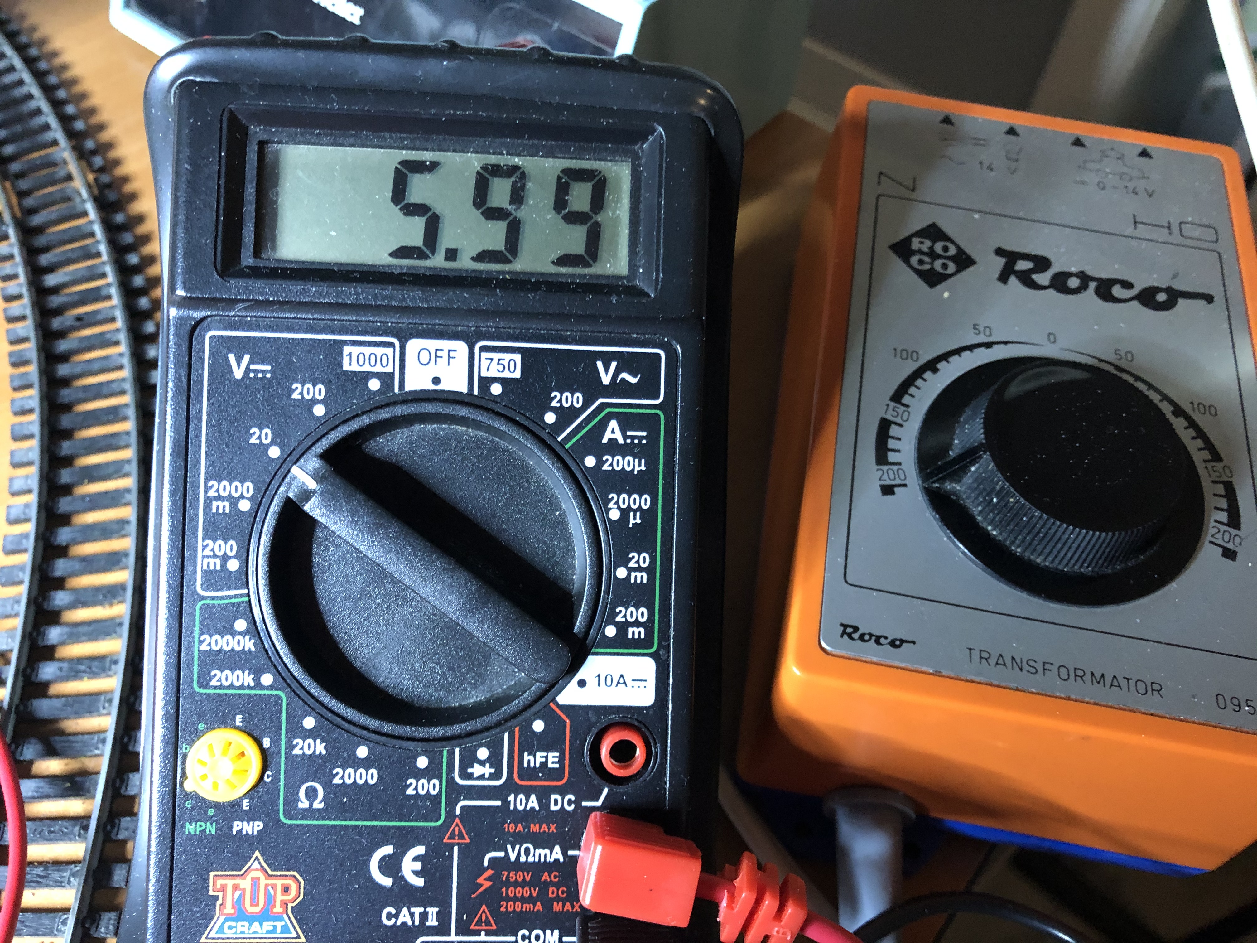 |
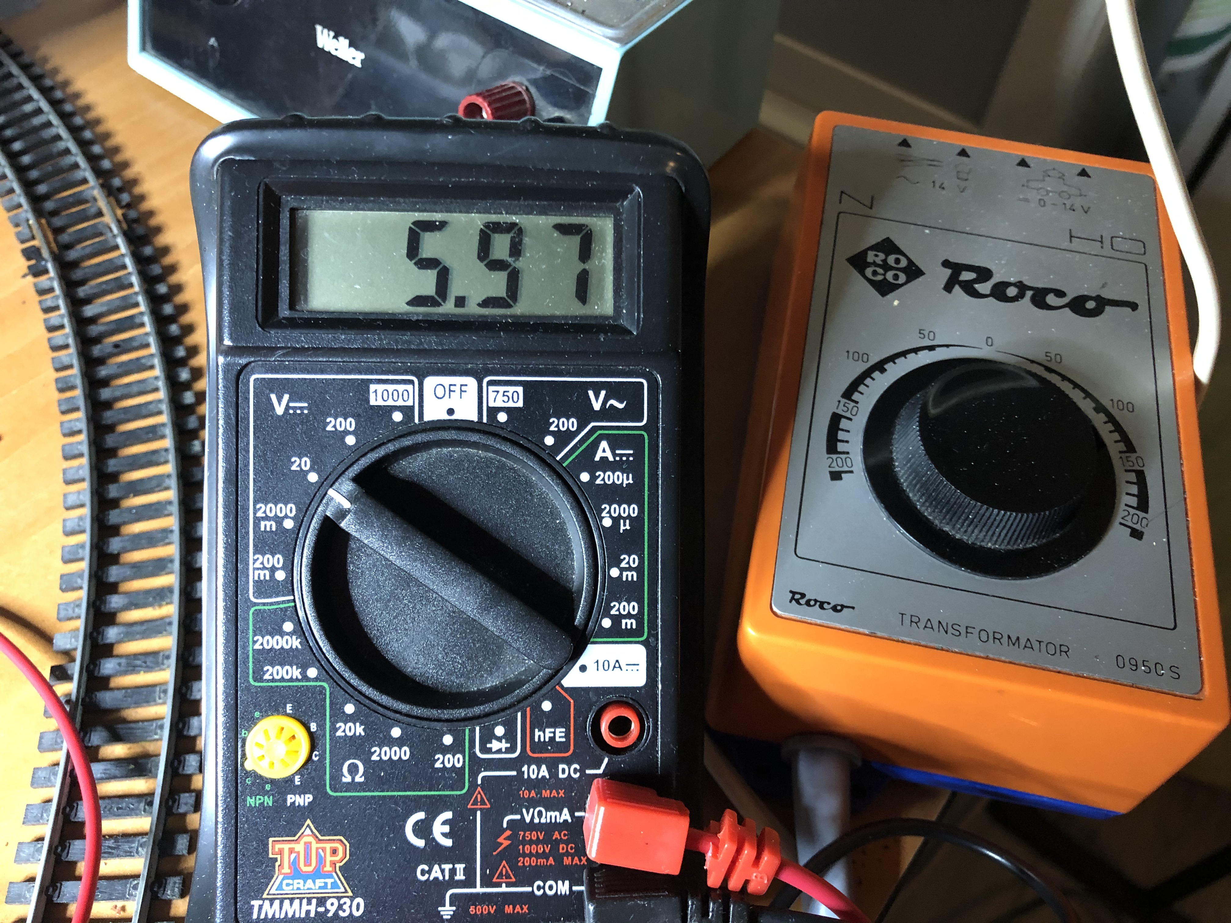 |
At full power only maximum 6 volts and polarity switched also 6 volts with same polarity as output
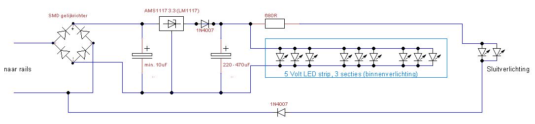
Here you find the drawings of the schematics I used for the carriages.
The capacitor of 10uF is not really necessary. When the regulator behaves normally you can discard it. Else fit it.
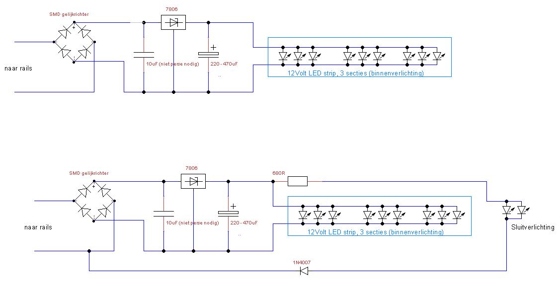
Two diagrams, only difference is the taillight added in the lower schematic
The end result.
The downside of the method above is, when you run your trains anolog, the light turns on just before the locomotive starts running.
I started to experiment with 5 volt LED strips (warm white). Using a standard LM7805 regulator will do the job. The light is too bright though.
Every LED has its thresshold before turning on. That differs per color and maybe brand. So, experiment first.
For the 5 volt LED strip I use a AMS1117 3.3 regulator. When you order these regulators, check the voltage. These are also available as AMS1117 5, which outputs 5 volt.
This is the schematic. With this regulatir you do need the capacitor of 10uF. Or else the regulator might respond strangly.
Components you need to build this simple project:
Piece of pertinax board
SMD rectifier
SMD regulator ASM1117 3.3
Diode 1N4001 or higher (I used the 1N4007)
Capacitor 10uF, 16 volt or higher
Capacitor 330uF or higher (depends on space in carriage)
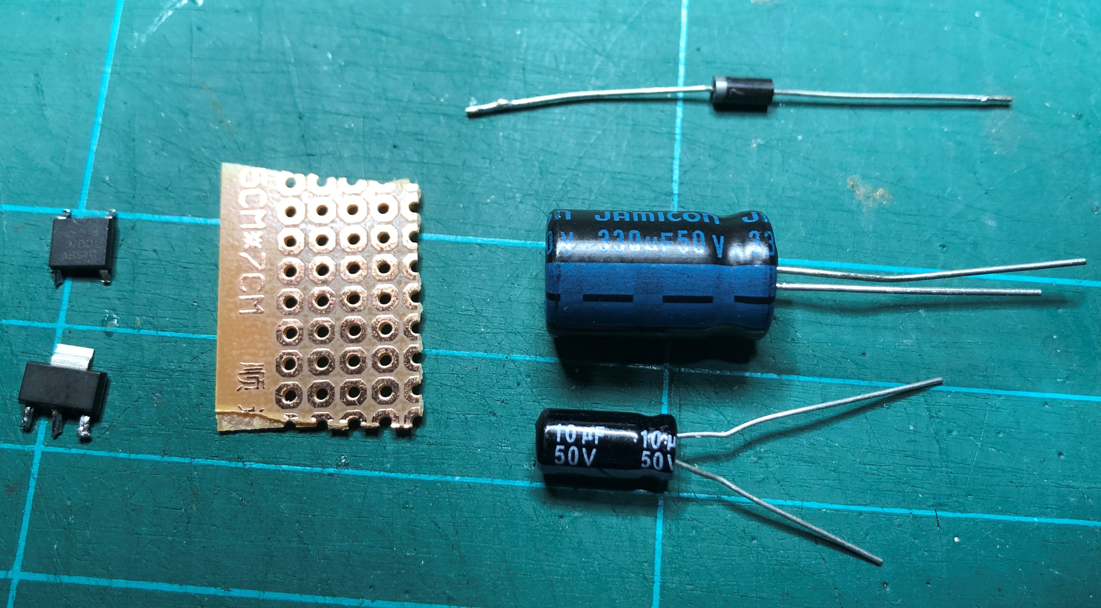
The component. Note: I plated the legs of the SMD components already, makes life easier
Bend the middle leg of the regulator (see picture below).
Solder the rectifier on the board. With the ~~ to the outside of the board.
At the opposite side of the board mount and solder the 10uF capacitor. Watch the polarity.
Solder the regulator and and connect the + and - from the rectifier to the appropriate legs on the regulator (outside legs).
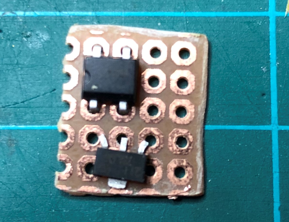
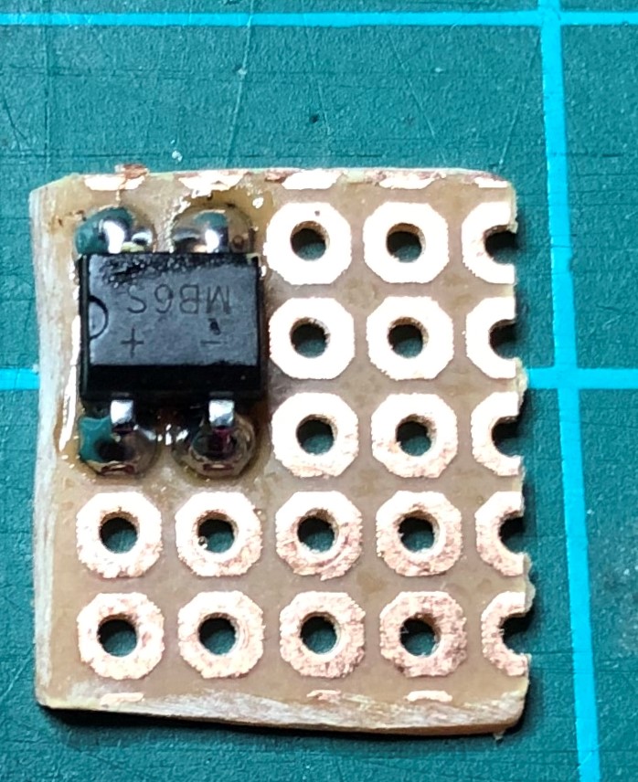
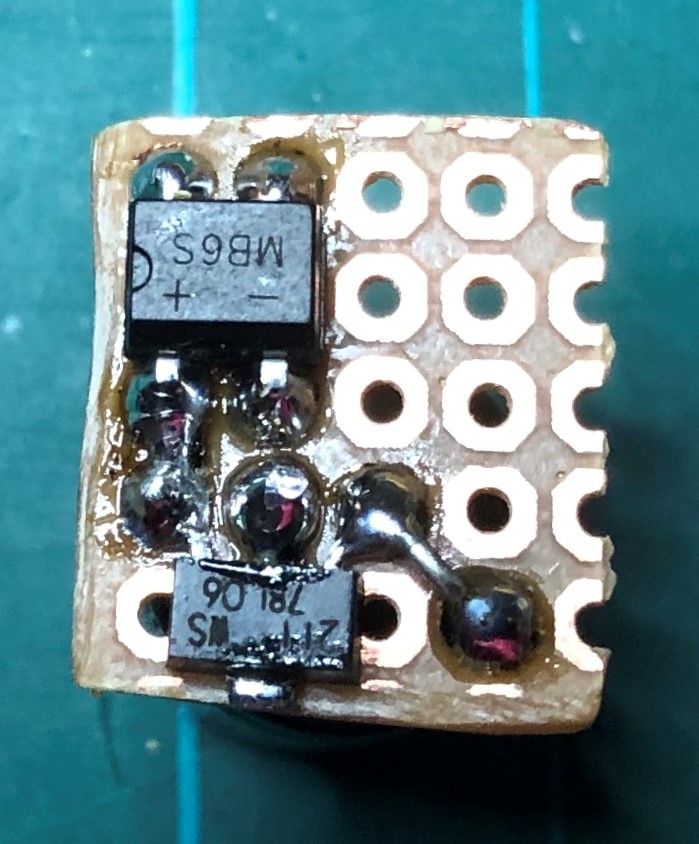
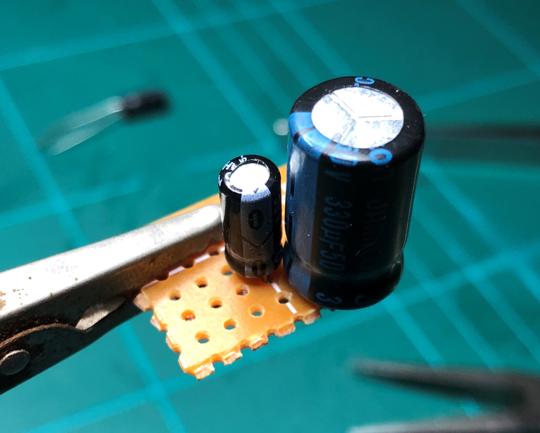
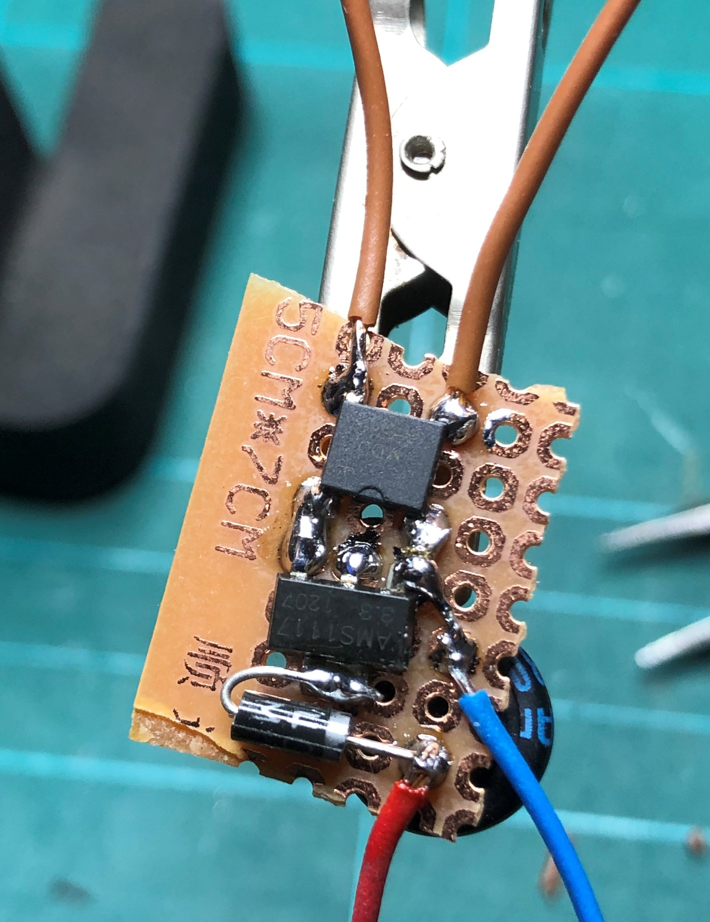
The cooling plate of the regulator is the + output. I use it to solder the diode to it. The other side is connected to the + of the 330uF capacitor.
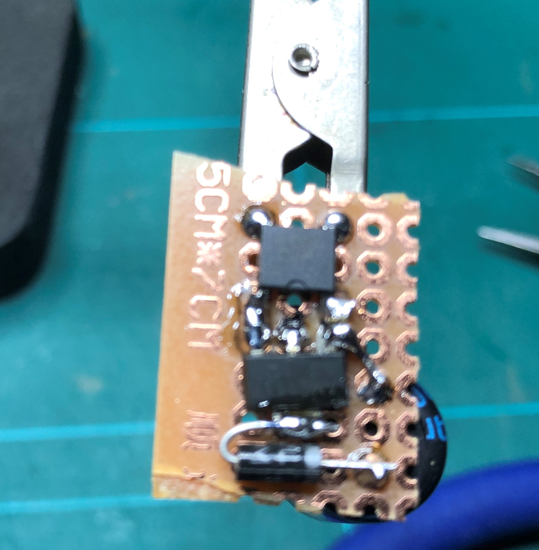 |
 |
Both sides of the board
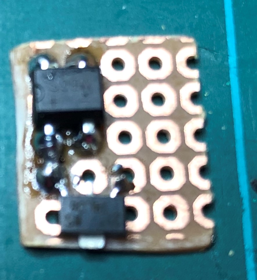
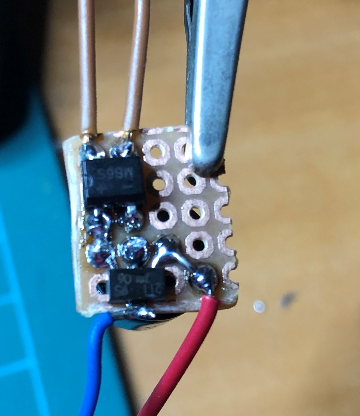
And of course test the board before mounting it into the carriage.
 |
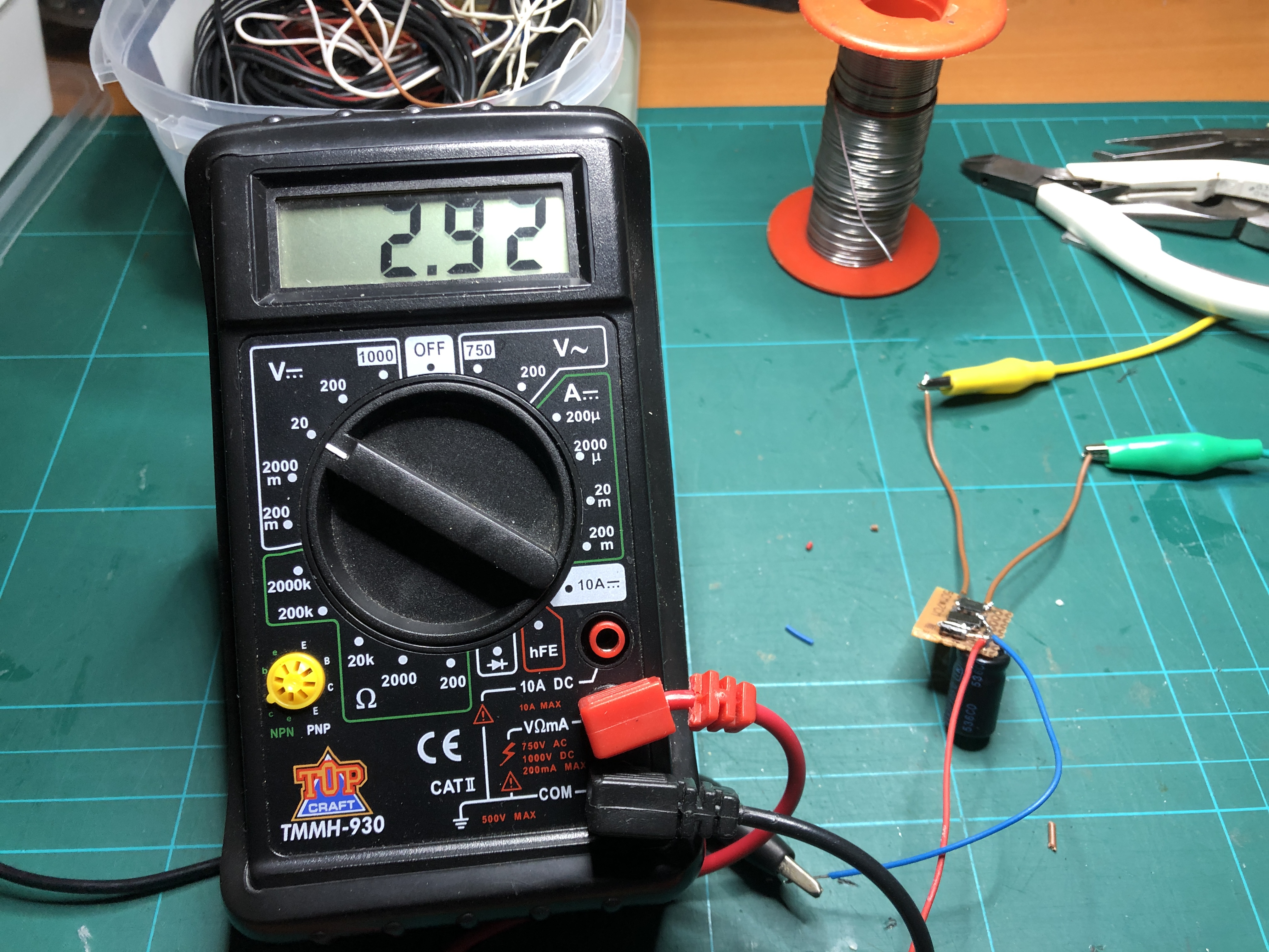 |
Board ready for testing and the result on the right
You might notice the output is only 2.92 Volts. That is because I added a diode in serie with the LED strip. The diode has a threshold of about 0.4 volt.
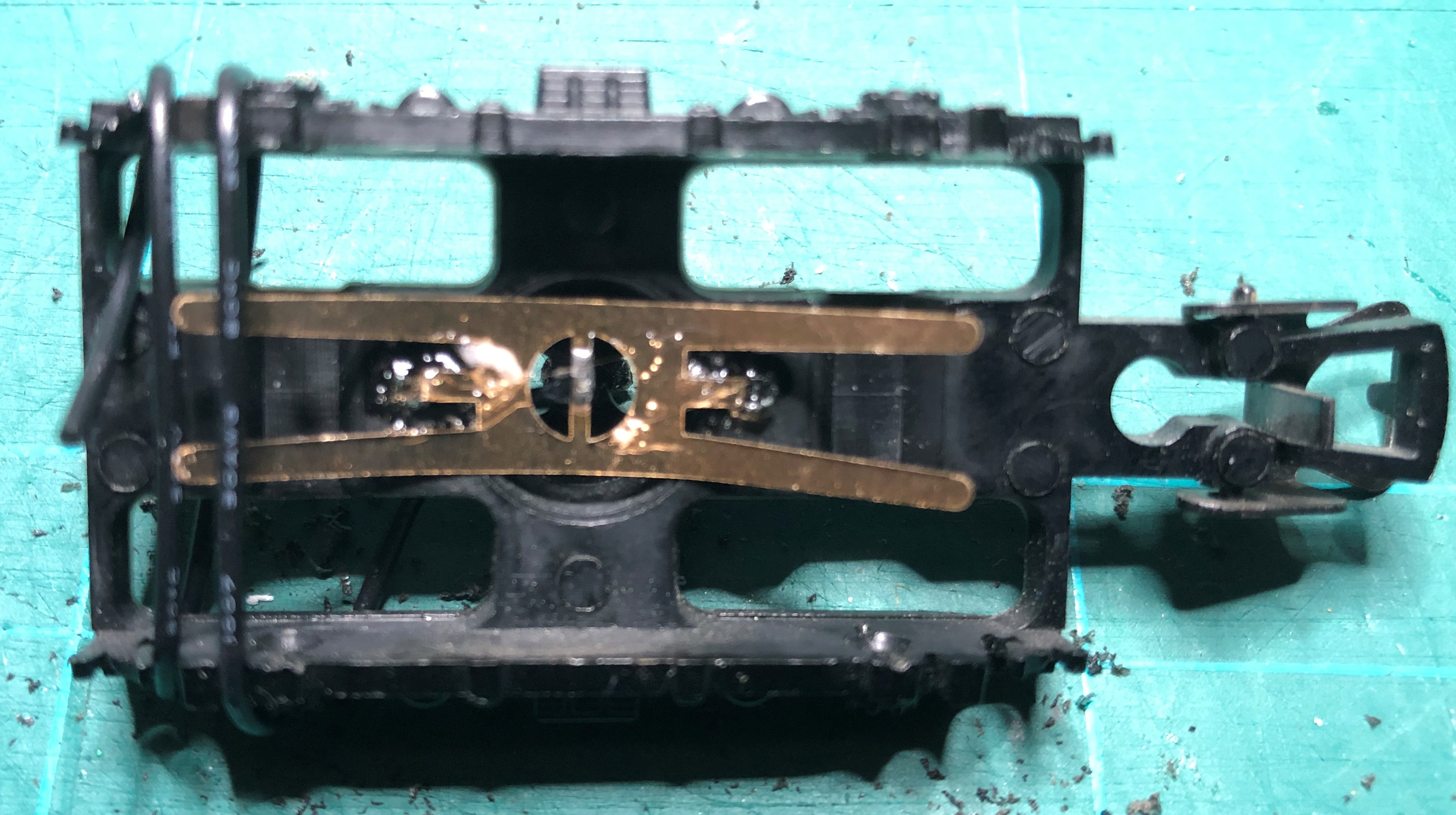
Time to take the NS, Plan E, carriage apart.
Remove the two screws in the bottom.
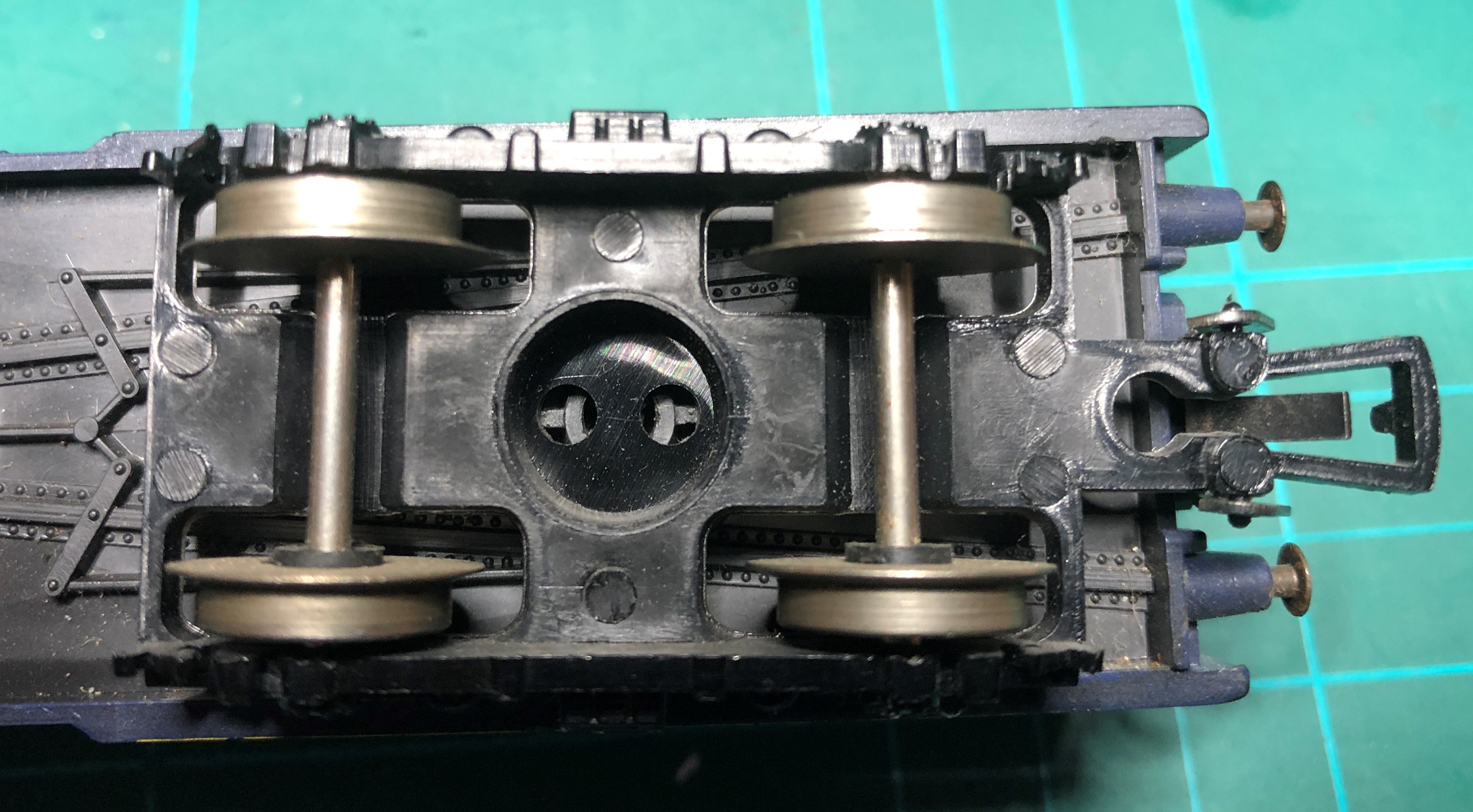
Remove gently the wheels from both the bogies.
Remove the bogies themselves by gently pinching the fixings in the carriage with needle nose pliers.
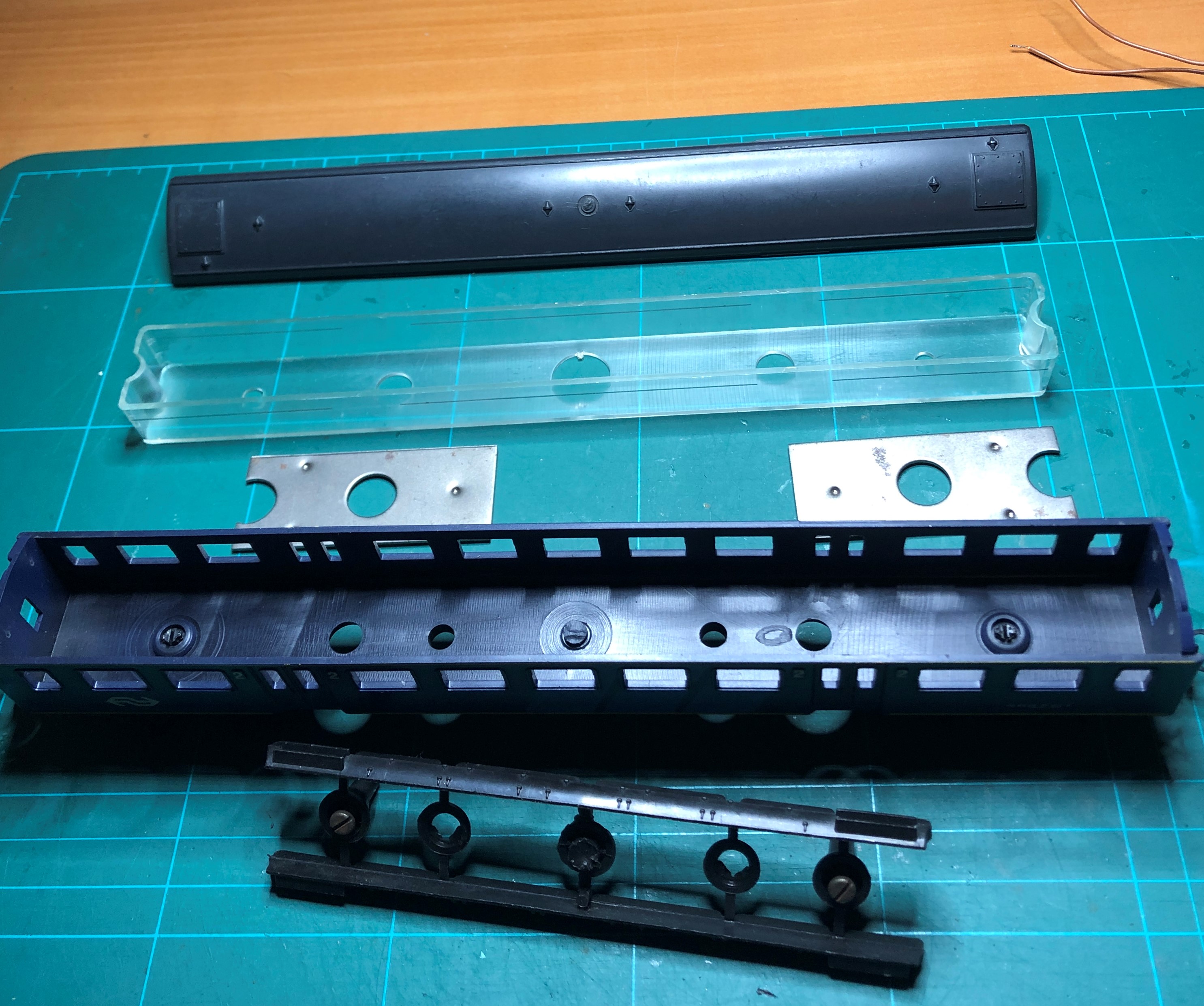 |
 |
Carriage taken apart and the bogie with wheels
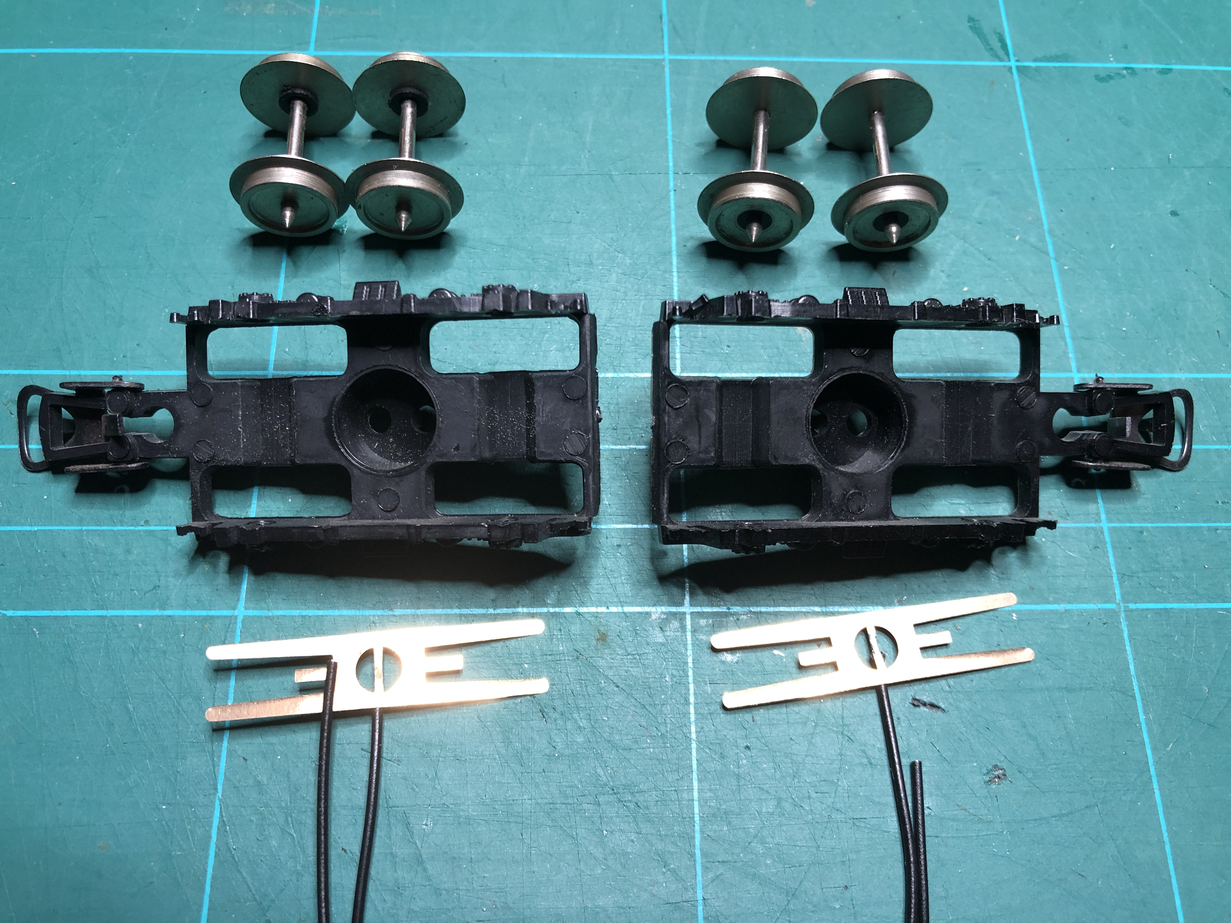
The disassembled bogies, wheels and springcontacts
Drill three little holes just near the shaft and one in the shaft, opposite to the coupler.
I used a 2mm hand drill. The wire from the springcontacts id led through the hole in the bogie.
 |
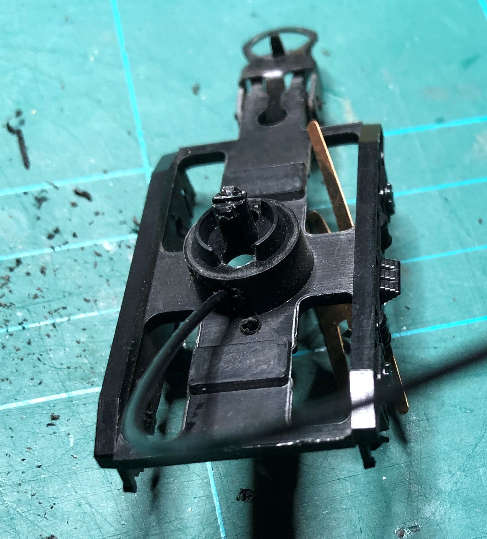 |
Holes drilled and wire led through the bogie.
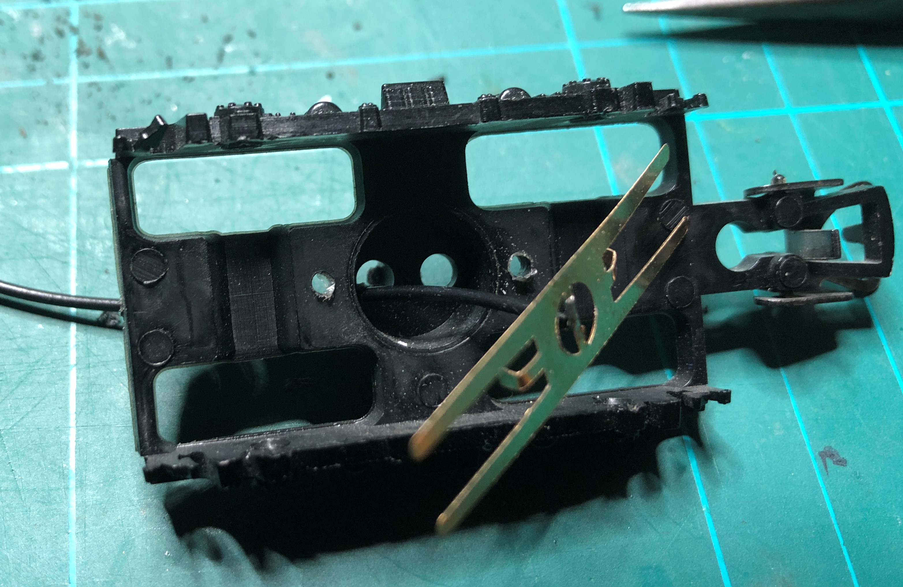
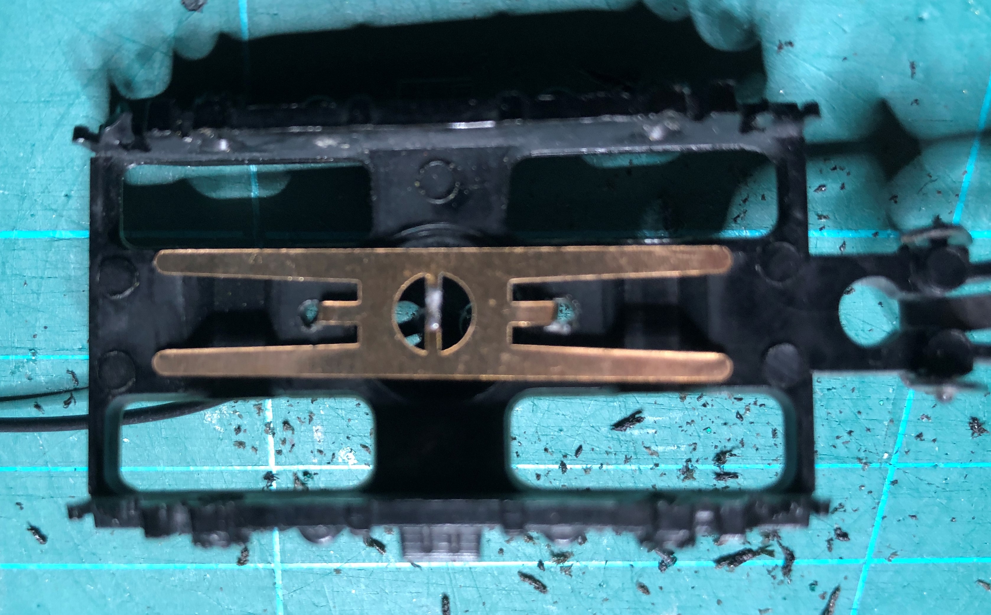
The two holes near the shaft are use to fix the springcontact in the bogie. I bend the two inner coppr strips so they fit into the holes.
Use a bit a of glue to fix the contacts in the bogie. Let it dry before mounting the wheels.
 |
 |
Contacts bend to fit in holes and on the right, the glued parts
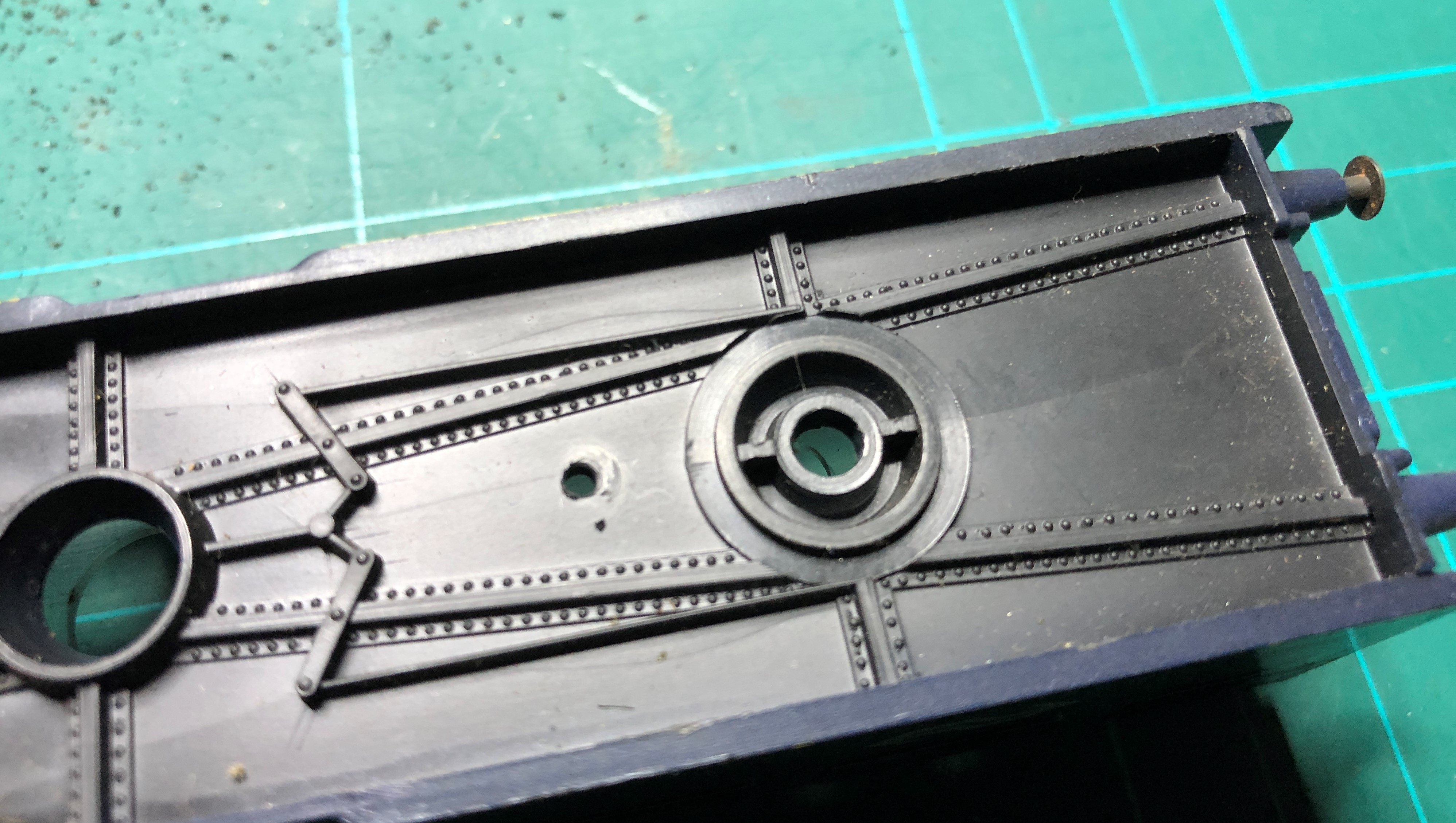
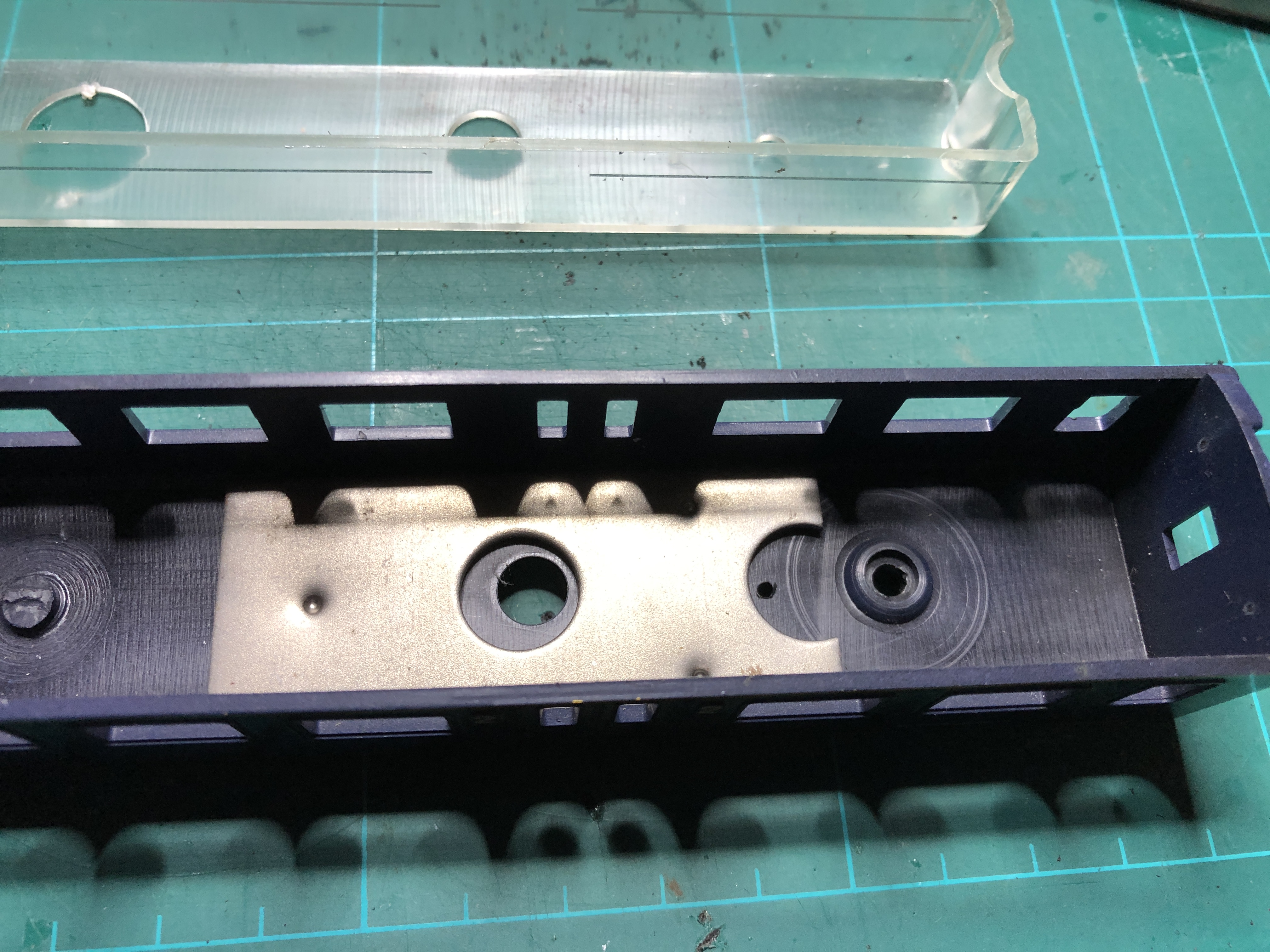
Drill a 2mm hole on both sides of the carriage. Best to leave the transparent container in while drilling. Use a sharp low speed drill.
Also take into account the location of the weights.
 |
|
 |
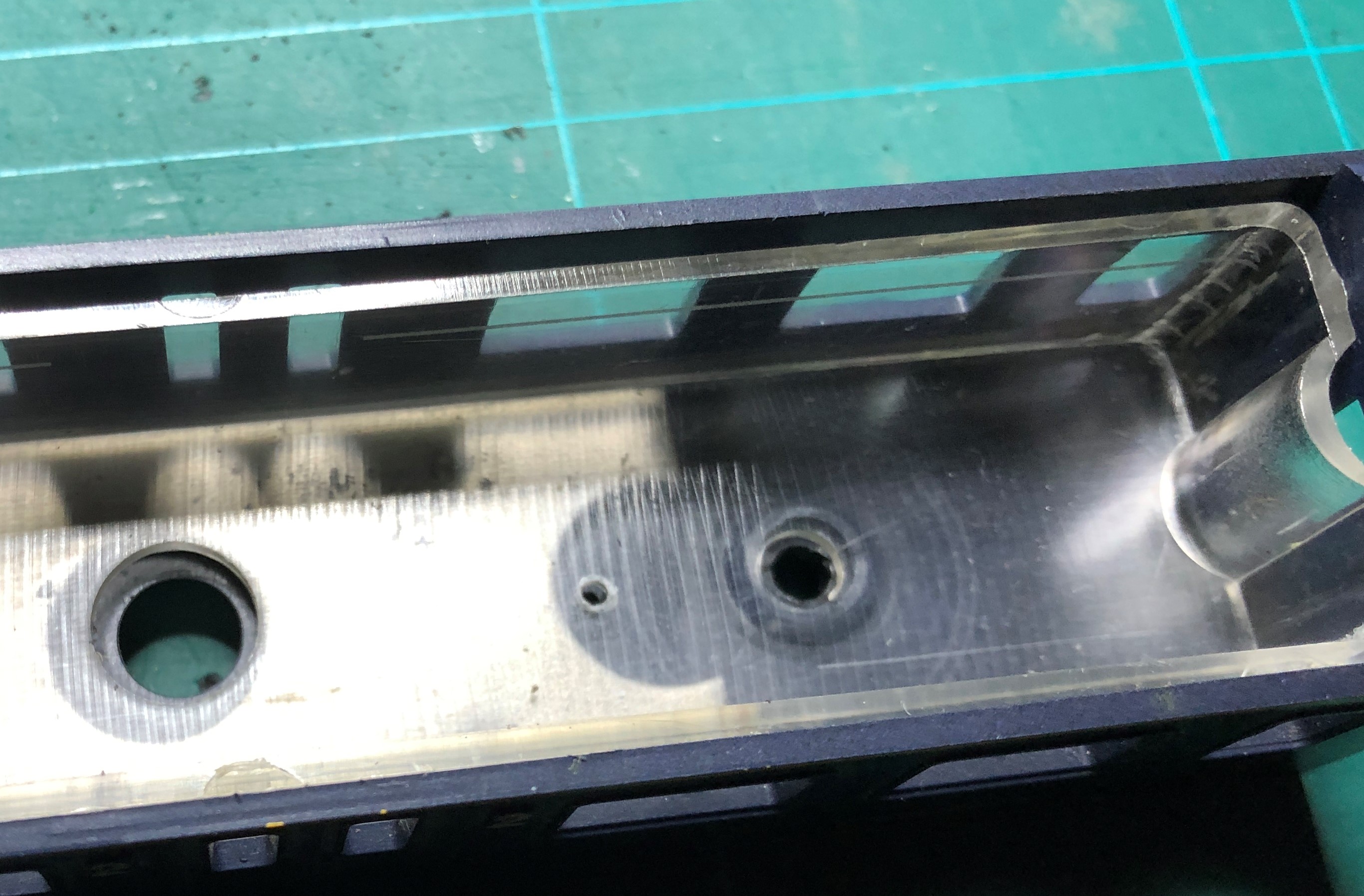 |
Holes drilled and their location
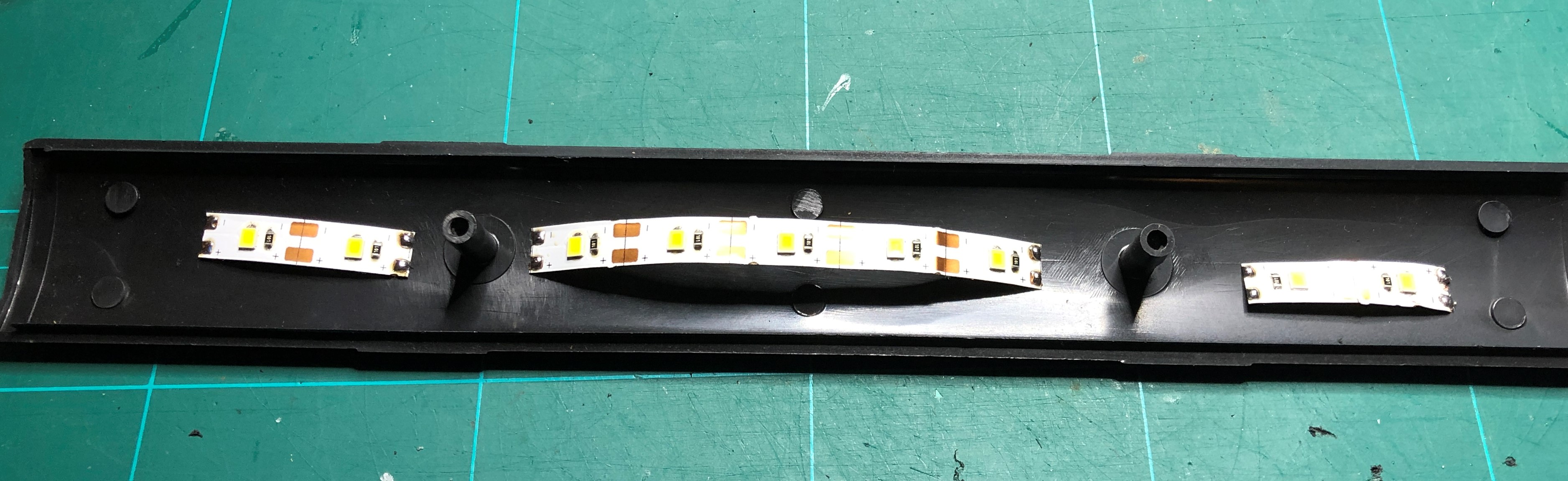
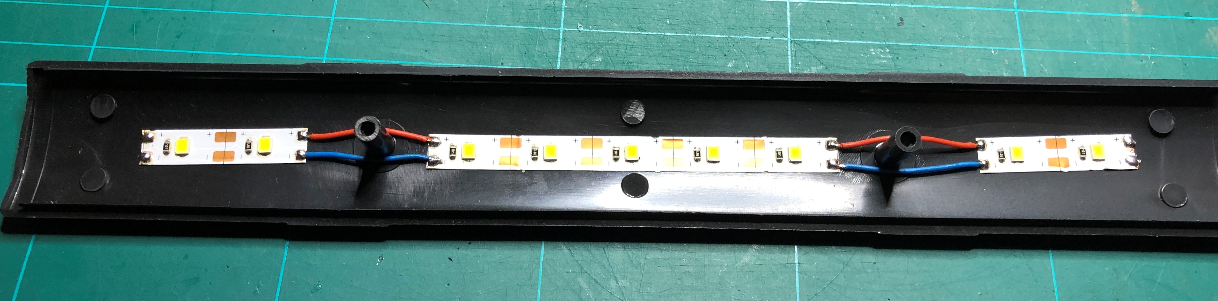
You might have noticed there are big hole in the floor of the carriage. These used to mount and screw the roof tight.
Therefor I have to split up the LED strip into parts.
 |
 |
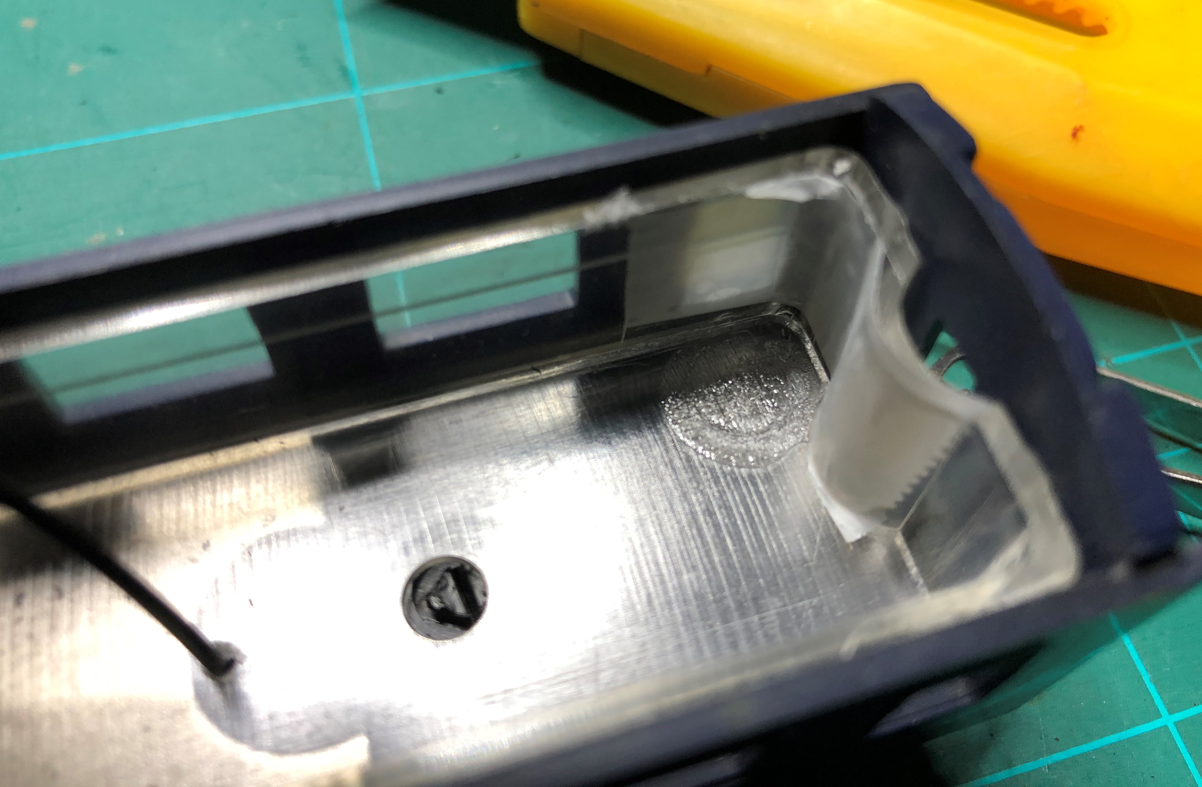
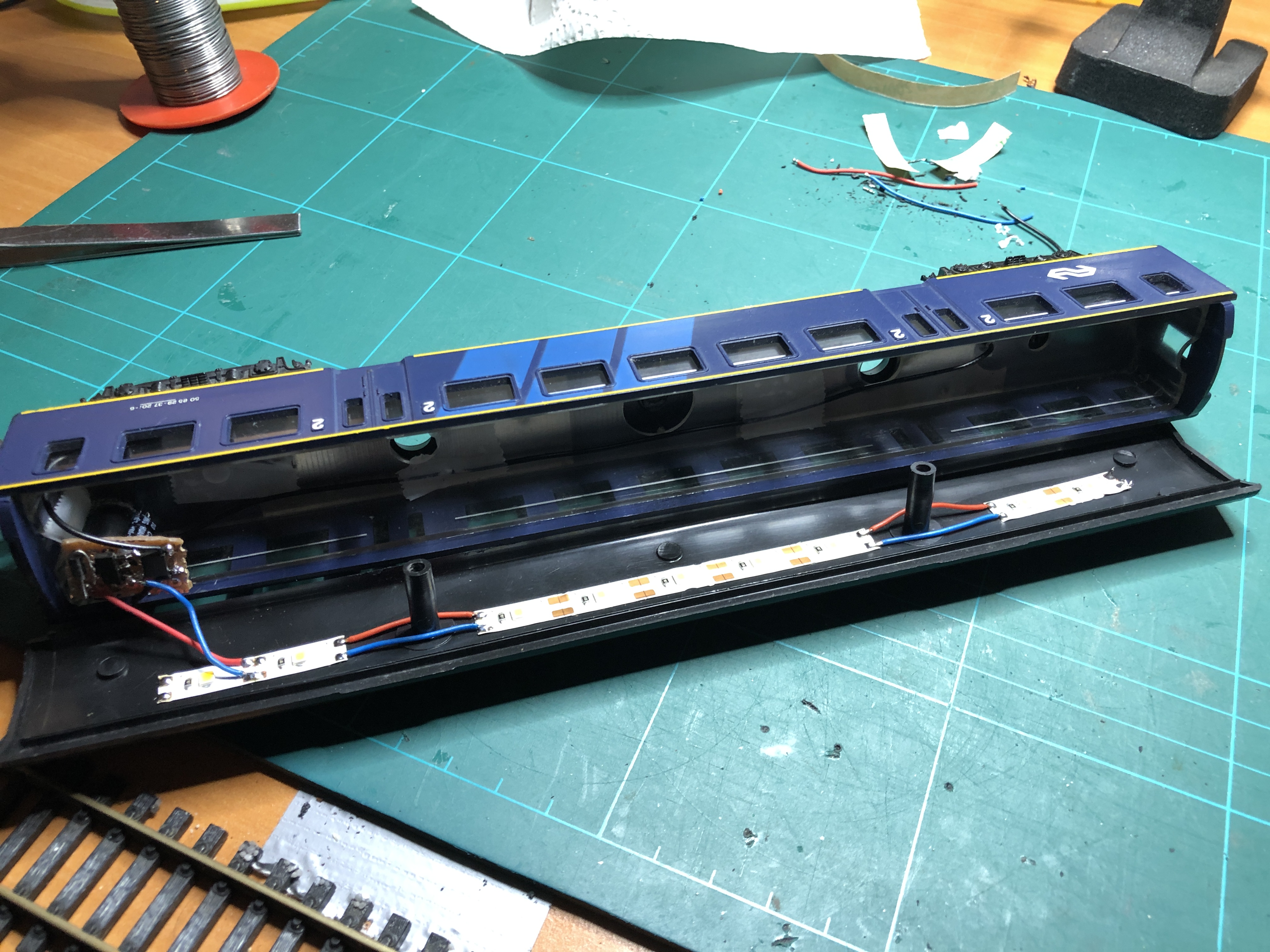
In the corner where the print is mounted the window is made milky white with some scotch tape.
 |
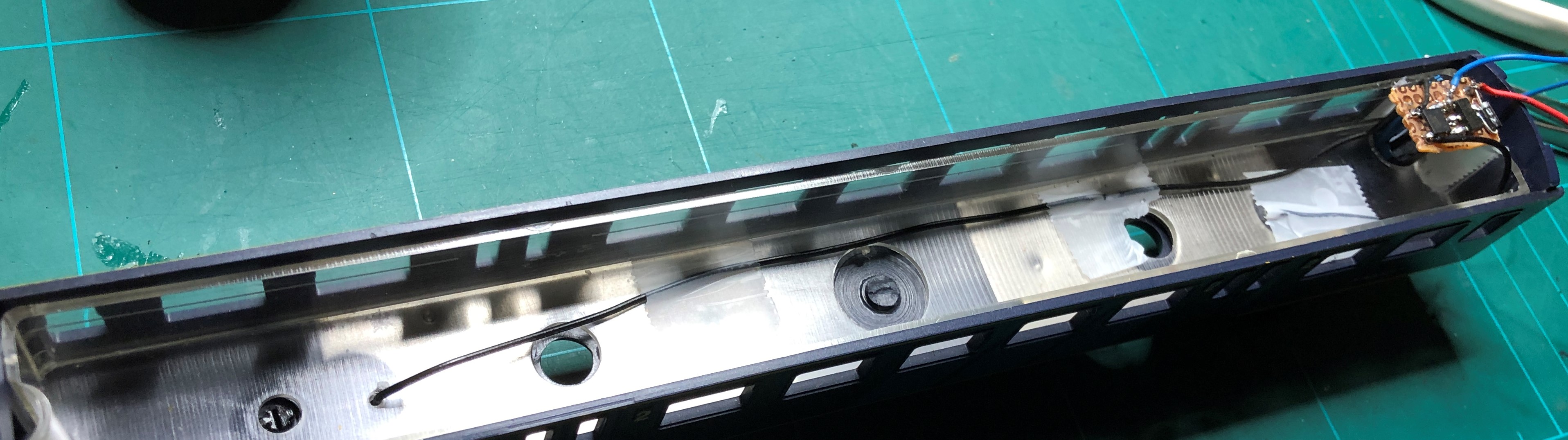 |
Print mounted in the carriage, roof not yet closed.
 |
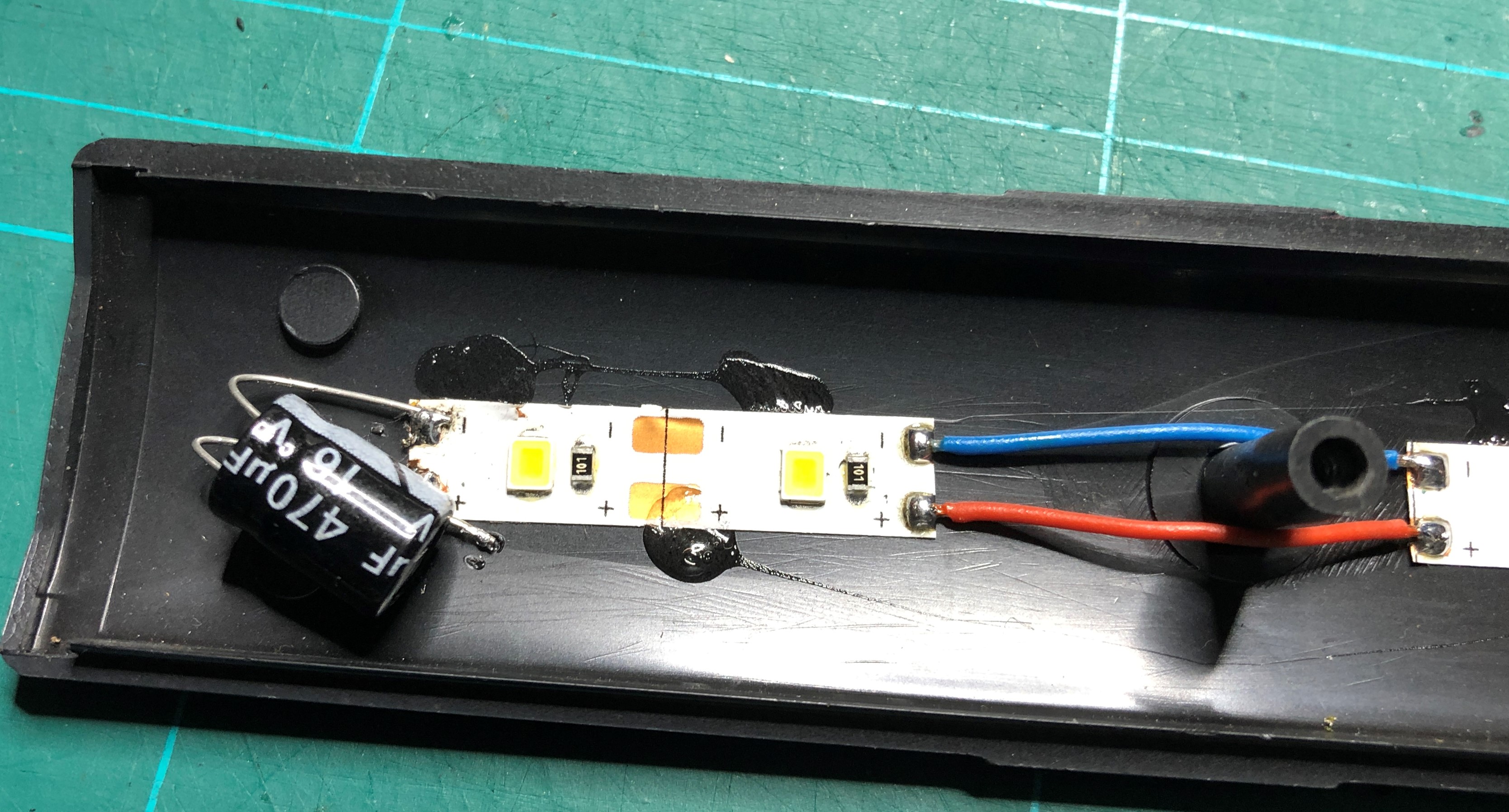 |
Added an additional capacitor of 470uF. This results in more stable lighting.
The end result.