
Model trains
The pictures can be clicked on to see them in the original format in a new tab.
 As a little boy I already loved trains.
My dad worked at the Dutch Railways (NS, Nederlandse Spoorwegen).
Got my first (plastic) train when I was around 5 years old.
Later I played with Lego trains. You could build them as you likes and also build houses, stations and scenery.
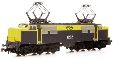
I think I was around 12 years when my father bought me a real electric HO model train. It was a set the retailer HEMA sold. In fact it was a Lima trainset.
After this nice present I was completely hooked. Started to save money to buy more. And when I was 16, I had a big table with about 22 meters rails, mountains, houses, river (real water), briges and many more.
Because I did not have much to spend, I build a lot of stuff myself with rubbish you would throw away anyway. I build trees, signals, scenery and more. Build in light in locomotives and carriages.
And then you fall in love, get married, have children. And don't have the money, time and space to continue this nice hobby. I always kept the rails, trains and buildings in boxes at my attic.
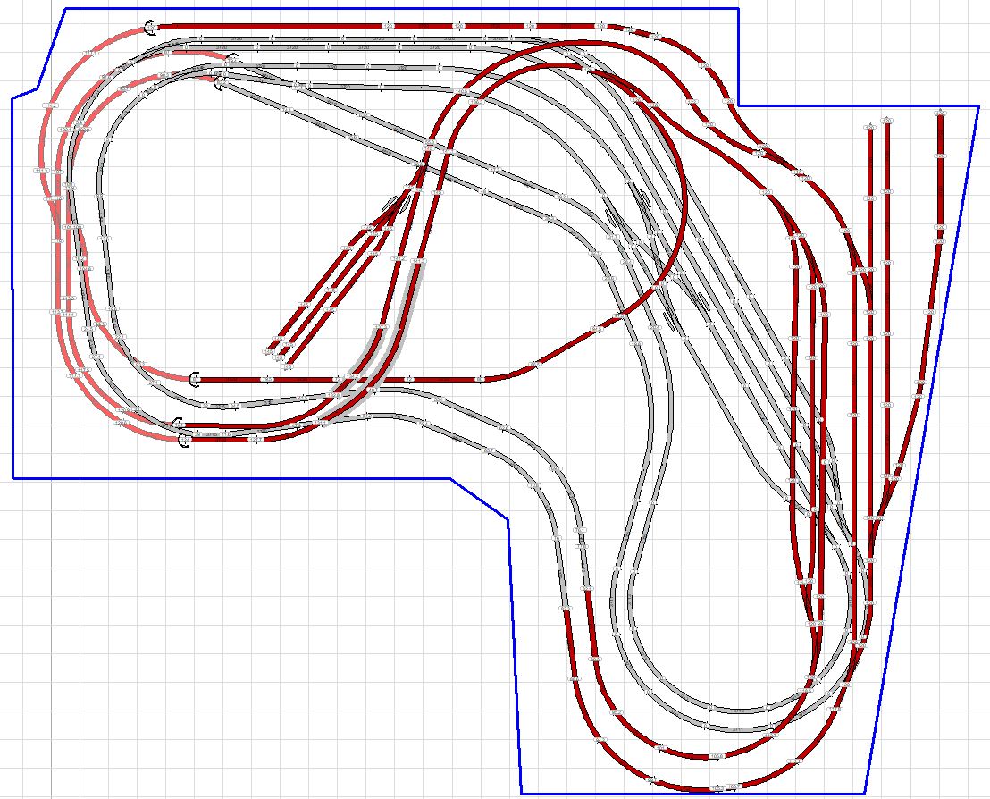
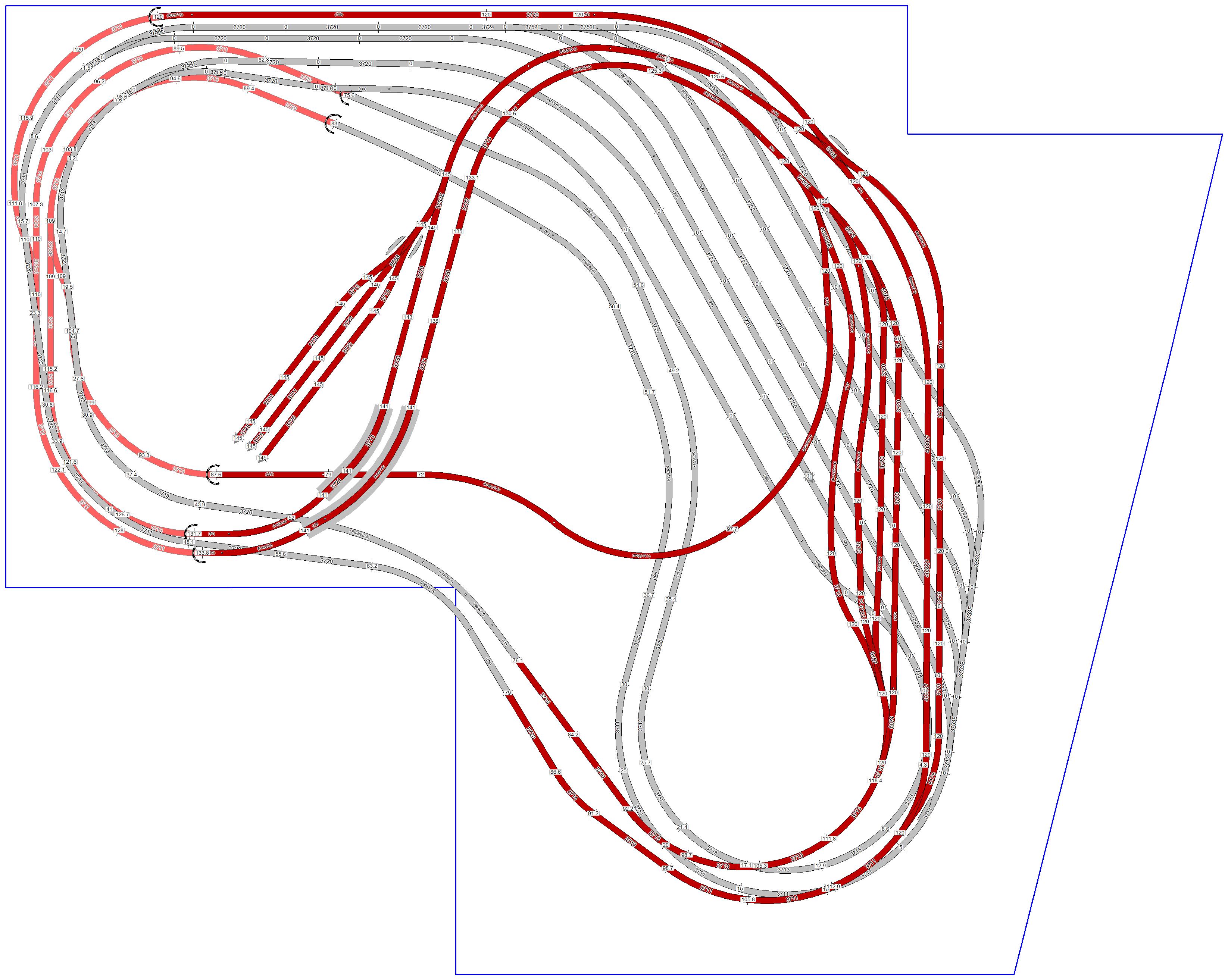
Now, in 2019, after more then 40 years, I restart this great hobby. Made a plan, see below. The idea is to start winter 2019 buidling a frame to put the rails on.
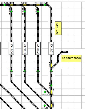
The gray tracks are the shadow station and the red(ish) are the top layer with the landscape. The light red are under the "mountain" I have planned.
Jump directly to:
July 2020
August 2020
September 2020
October 2020
November 2020
December 2020
Januari 2021
Februari 2021
March 2021
June 2021
August 2024
November 2024
First plan.
Plan has changed a bit. Could not fit it in the room.
And even when I started building the frame, I noticed I could not reach all locations on the layout.
So, decide to change it again.
The current plan, End July 2020
Despite the high temperatures in the Netherlands I continued building. Simply could not resist.
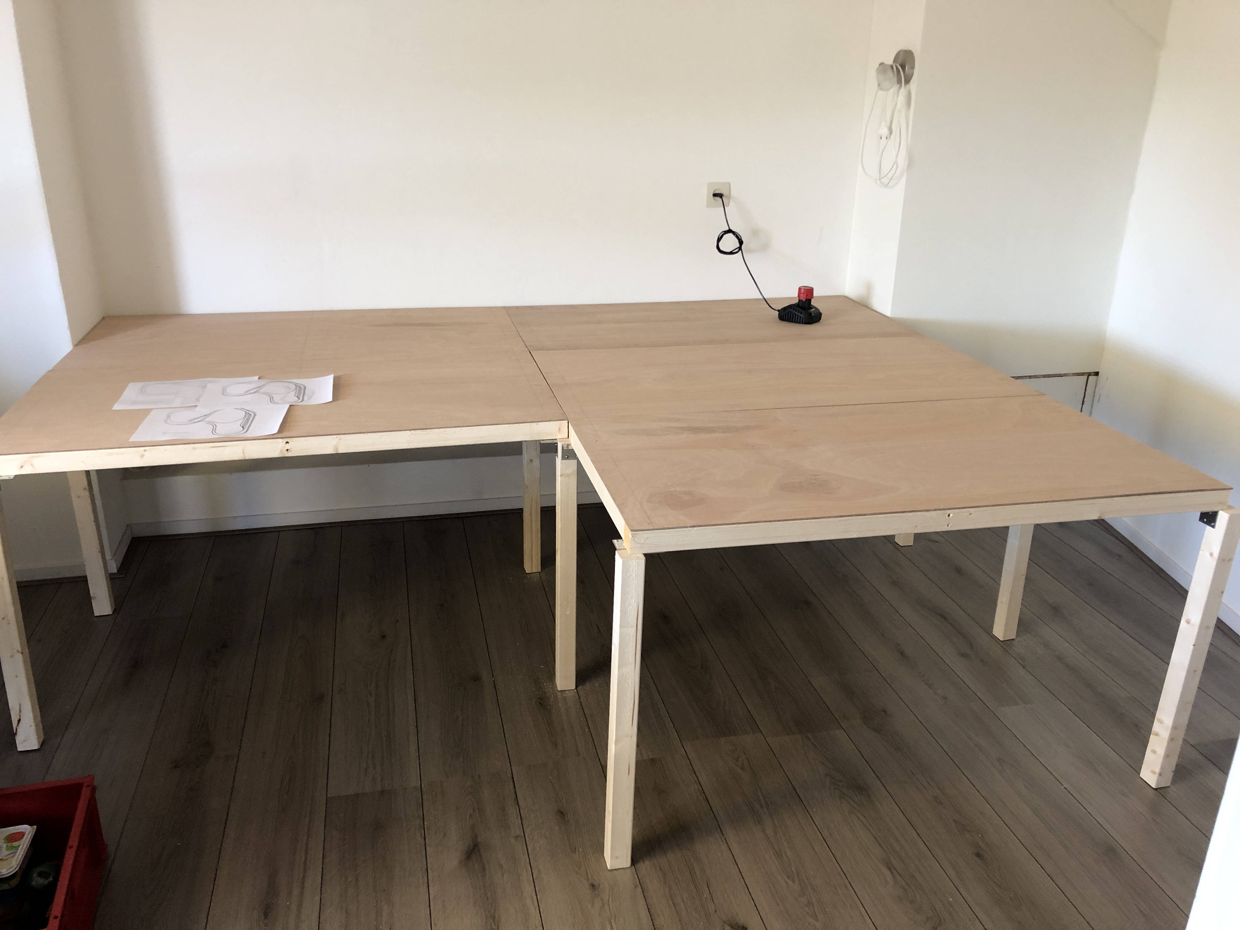
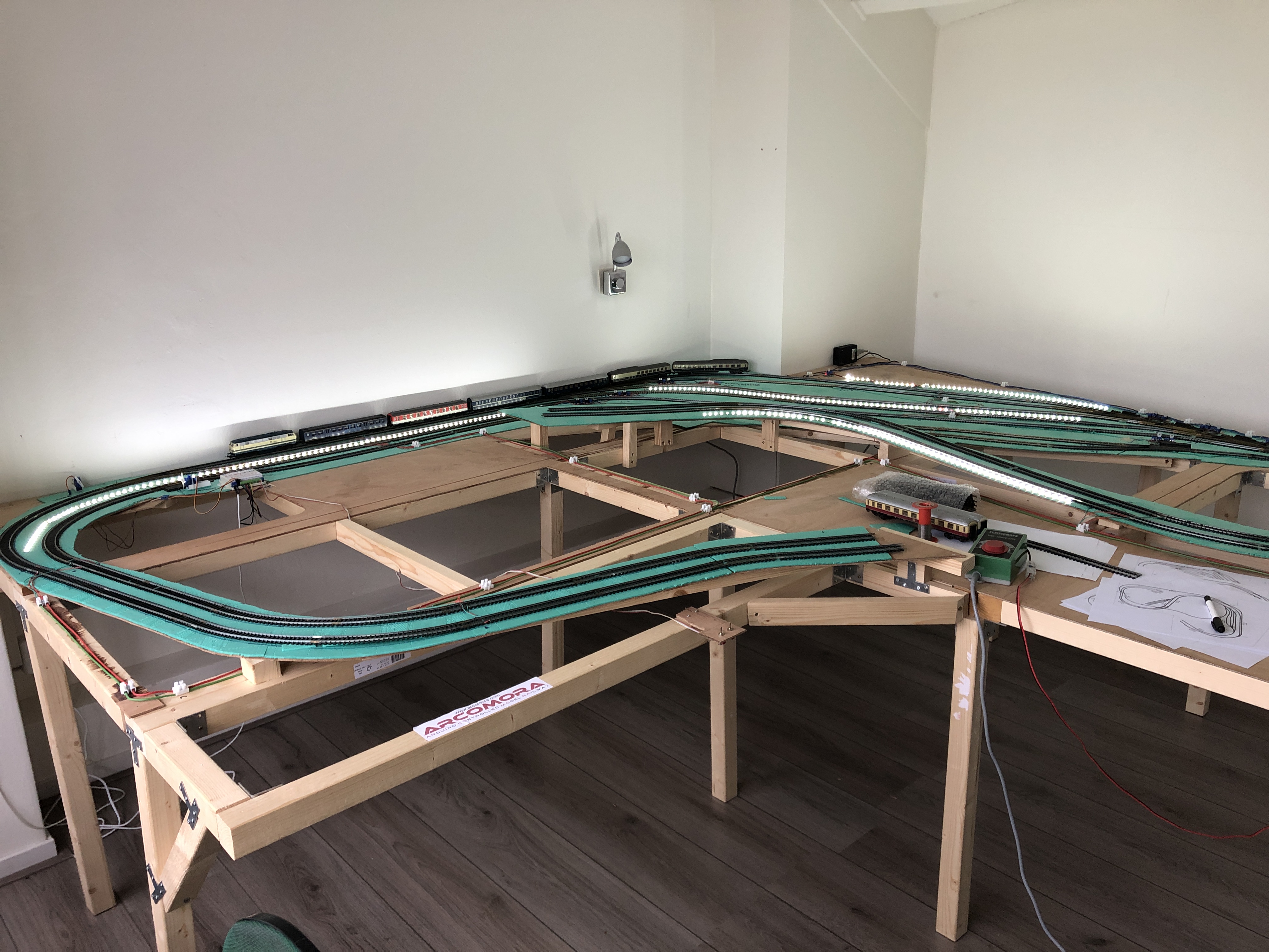
The start, five segments are ready
Now need to add some custom made segments.
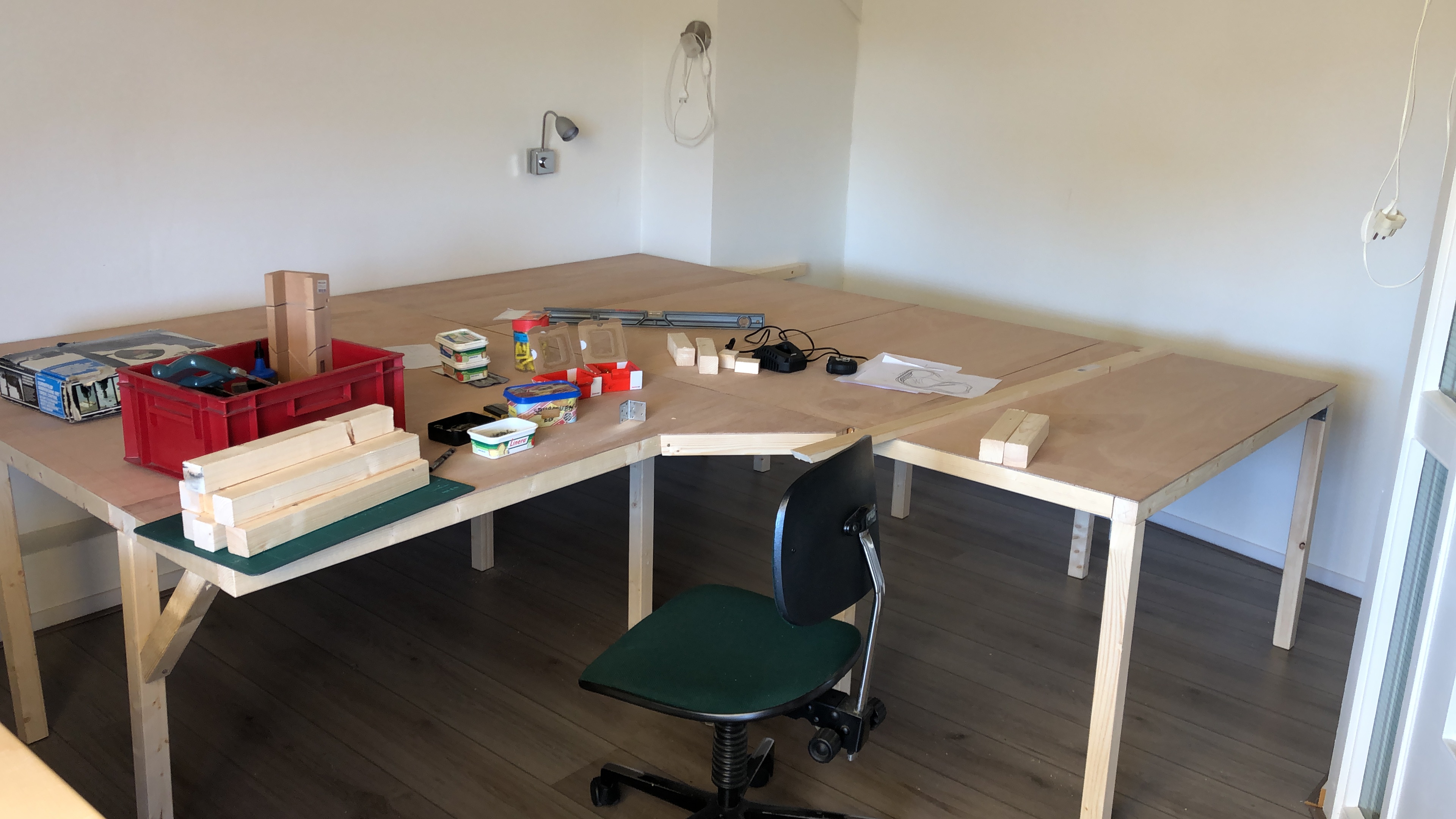
Almost finished with the lower layer
And added the tracks for the shadow station.
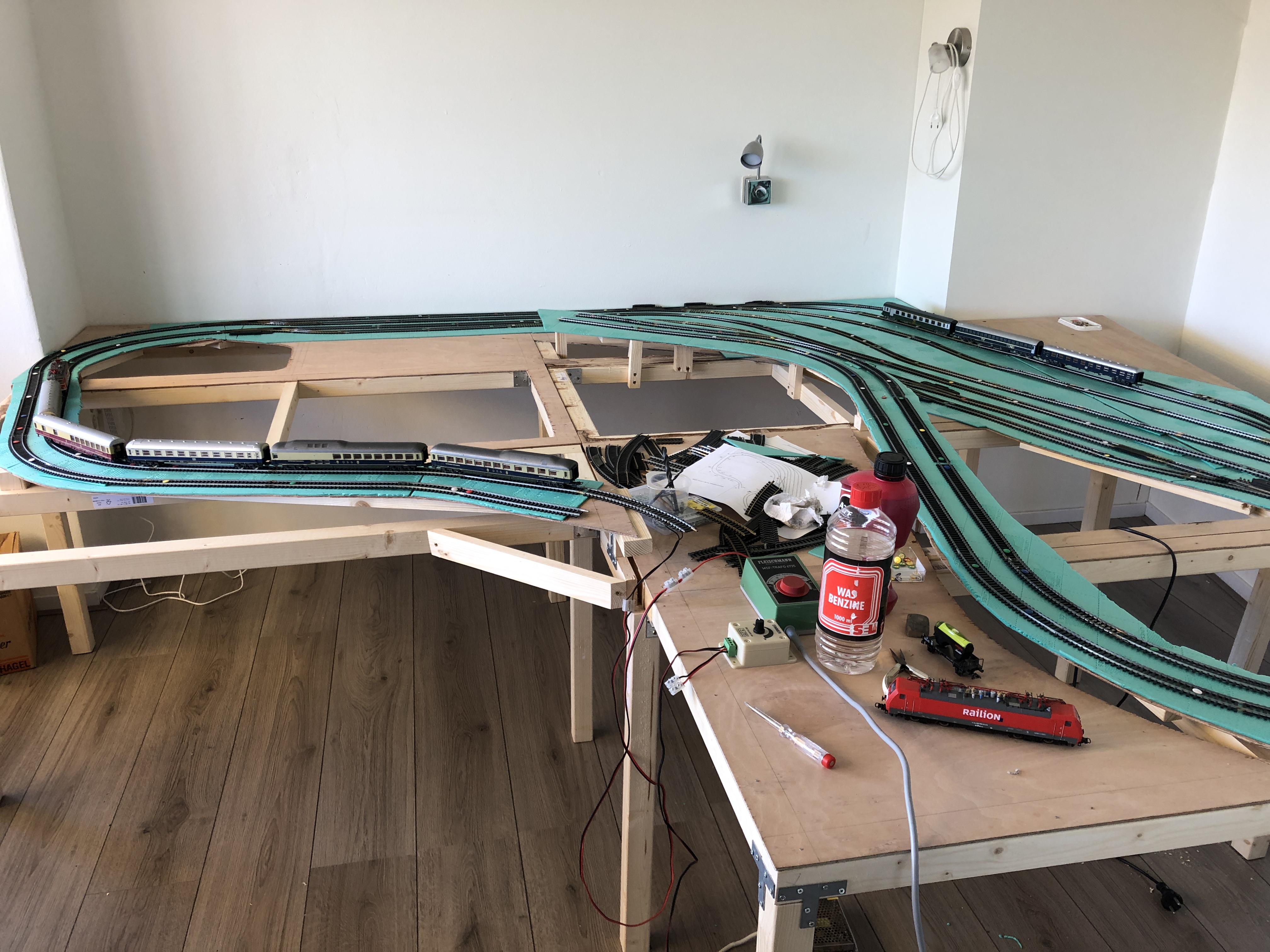
Added foamboard and rails
And did some test with different locomotives and carriages.
The slopes are OK and don't exceed the 3%. Train(s) can pull up to 8 carriage.
Notice the rails have not been definitely mounted. I used water diluted wood glue for the green foam board and pushpins to fix the the rails temporary.
When all test running were fine I glued the rails to the foam with the same water diluted woodglue.
In the back/middle you can see acrossing between two tracks. I removed it, because it did not make sense. The blocks would be to narrow for trains to stop.
See my initial and second plan.
While test running the trains I had to manually switch the switch. Twelve of the fourteen switches are old style electrical switches. I did not connect them yet.
Because space around the table is limited, I started to experiment with servo's and an Arduino.
Read more about the experiment.
Next step is to make sure the DC power (later DCC power) is properly distributed over all the tracks.
I kept in mind where I wanted my blocks and made connections accordingly.
The power lines are on top off the layout, because this is the shadow station and you won't see it later when level 1 is mounted.
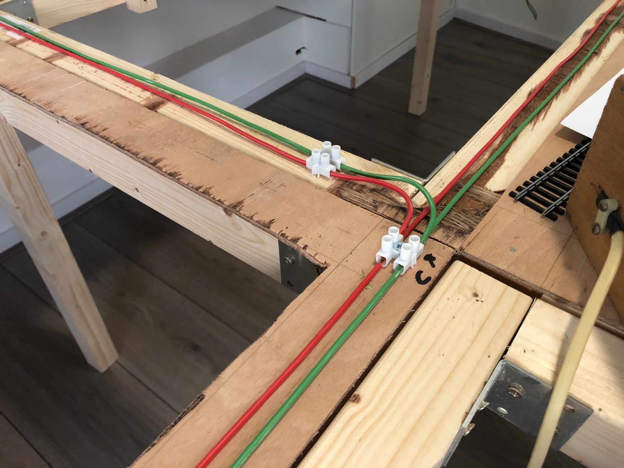
Red for plus and green for minus
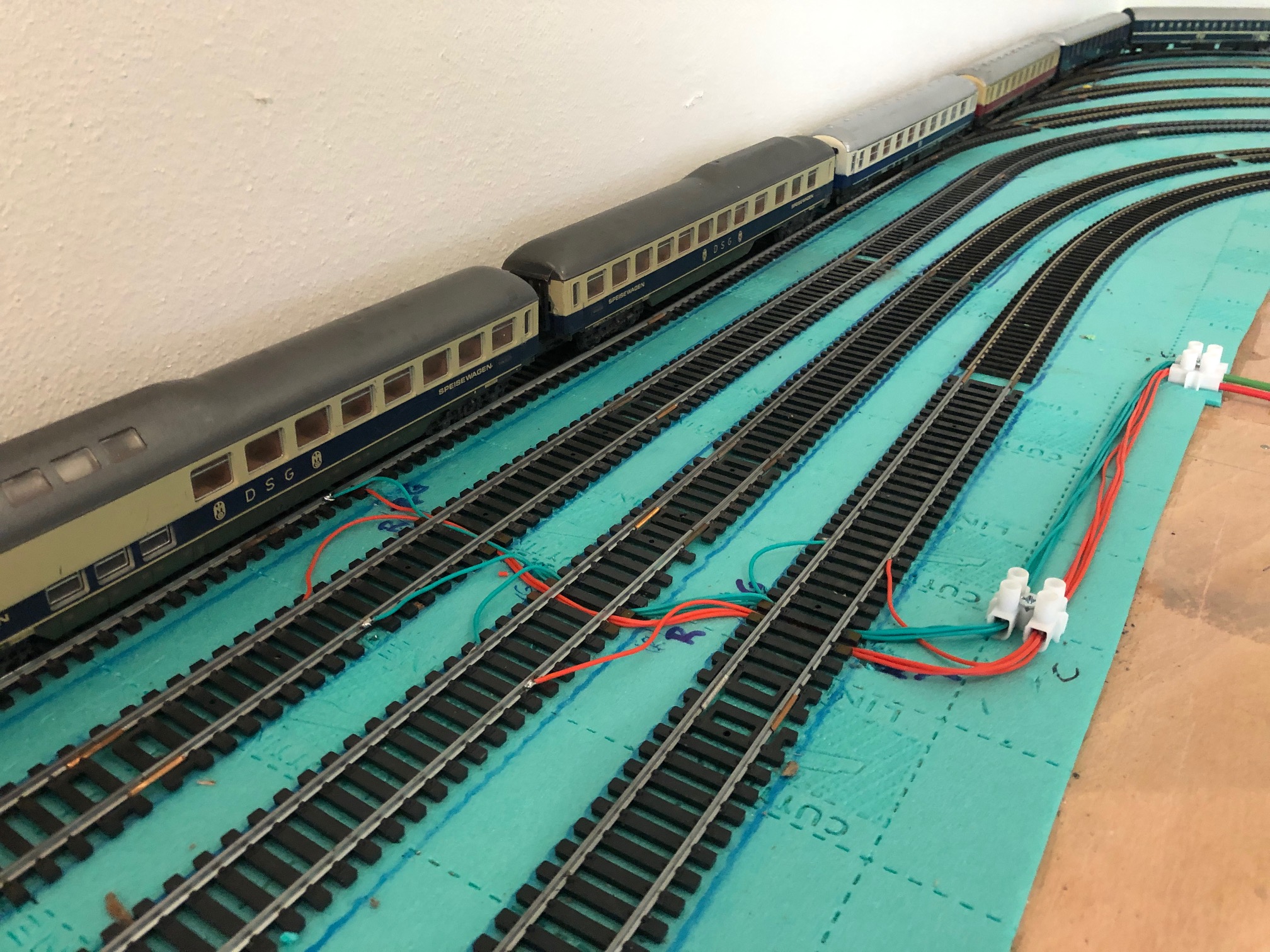
Detail, soldered the wires to the rails
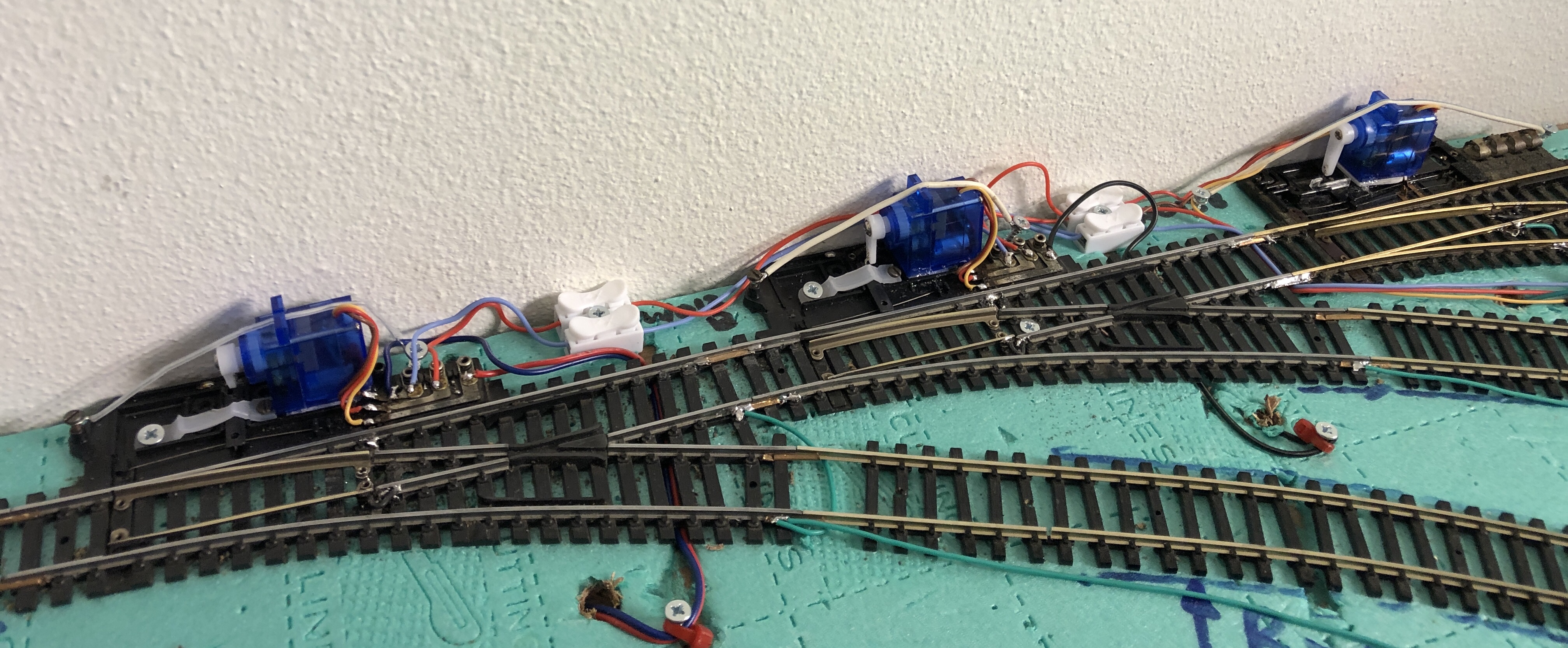
After some testing Arduino code to control servo's to turn switches, I finally installed two.
Both are hand control switches with different ways of operating. Hence two differen ways of mounting the servo.
The right switch is a real hand switch. And I used the mechanism that came with it.
The left switch is a hand switch that can be controlled by a solenoid device too. I just used the lever that came with it.
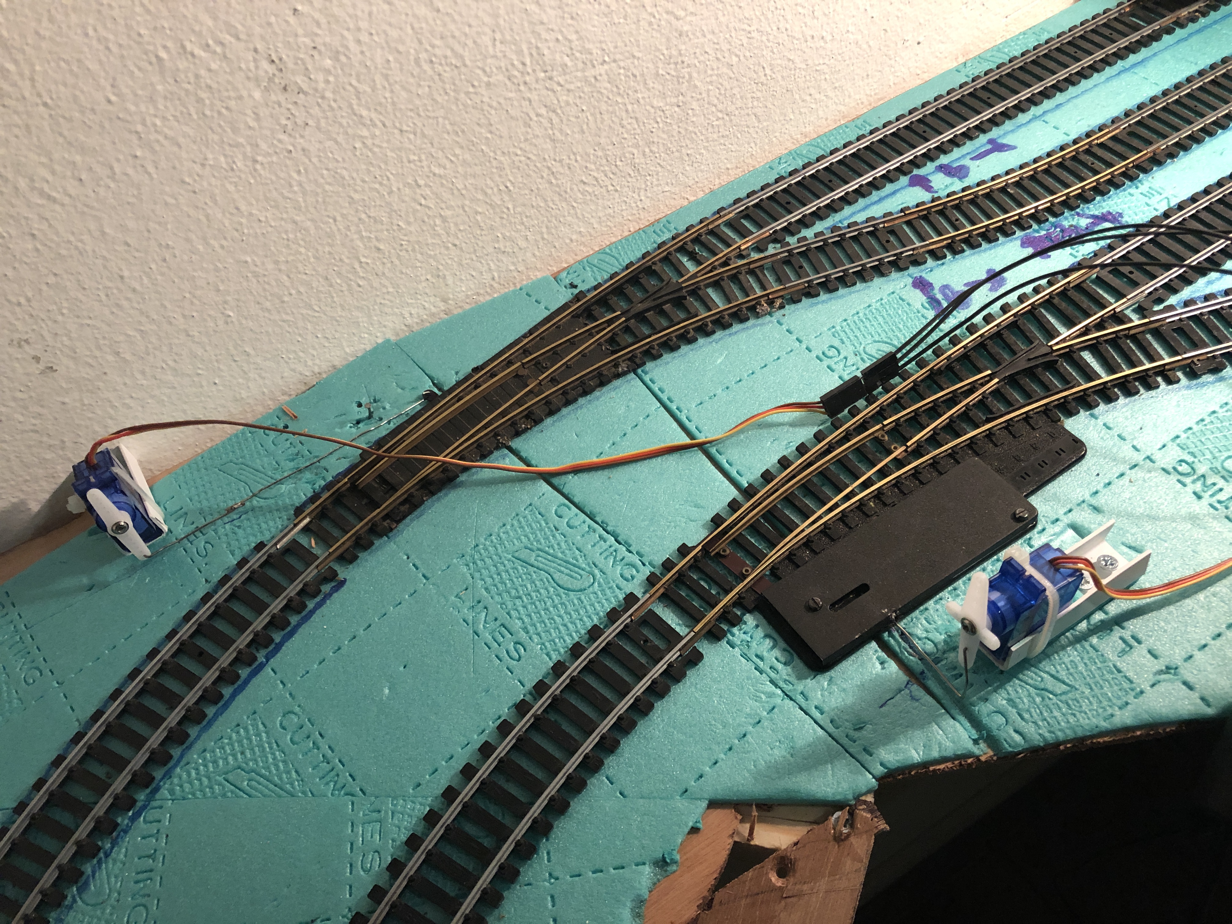
Both servo's are mounted on top of the board, as this is the shadow station, you won't see them
Right switch operated
On a dull Saturday afternoon and nit much time I decided to mount LED strips on the lower layer. So, when the main track will be build on top, I can see something, when I need to.
The LED strip is a 12V DC type and it is powered by same power supply as my switches. The DCCnext decoder can not power the strip directly. I used the same MOSFET prints I used for the switches.
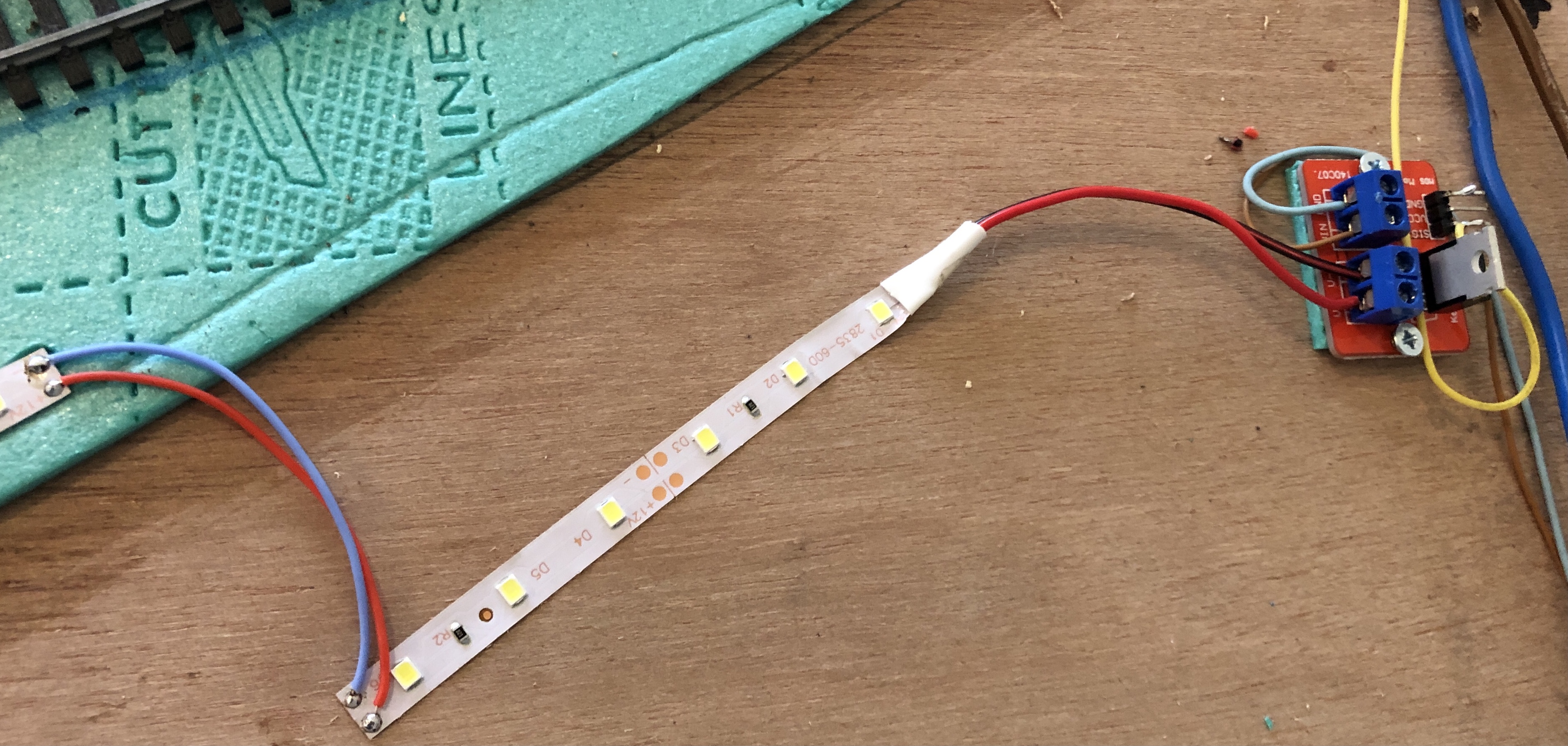
Above the, first part, of the LED strip. It is connected to the MOSFET print. The yellow wire is coming from the DCCnext.
Below all LED are on.
Also been busy with the second DCCnext with the Arcomora Mardec software.
The DCCnext will switch the other five switches.
All switches at the top left are now connected. The switches on the right will have their own DCCnext.
A friend of my suggested to try the free program Rocrail.
I did and had some problems with it. My train suddenly went full speed and I was just in time to grab it from the trachk before it would fall of at the end.
Or, to be honest it might have been a configuration option of the loc decoder. More about that later.
I returned to JMRI. At least I could test my Marcdec configuration.
I use JMRI to run my trains and operate my switches.
JMRI is very user friendly and I could easily control the lot.
Also created track plan in JMRI. Simplicity rules. Not really nice looking.
Below an the setup I made (sorry shot from the computer screen).
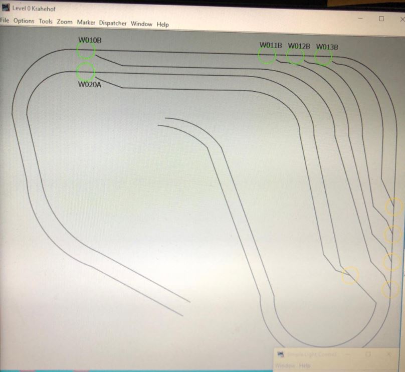
The switches can be controlled by clicking on it. And create a route so all switches are set to the right position before the train starts its journey. A disadvantages is there is no feedback from the swicthes. That is not so much a JMRI problem. You just need more expensive switches or add something yourself.
What bugs me about JMRI is I have to open all those windows by hand. It should be possible to do that with a startscript. Haven't found out how.
On the Benelux Spoor forum soneone mentioned he could not operate switches when the train is running. He used Rocrail.
I tried the same with JMRI, and had exactly the same issue. JMRI is connected to a Arduino Uno with a motorshield. The protocol used is DCC++. As decoder for the switches we both use the DCCnext.
As soon as my locomotive runs, the switches cannot be operated.
to find out what the problem is, and the solution, I first reconnected my DCC signal on a more professional manner. Bummer, did not solve my issue.
The DCCnext will switch when I use the input pins (I left them there in case of. This case
![]() ) and pull them to ground. So, it is not the DCCnext hardware, nor software. It must be the DCC signal that has spikes or other problems.
) and pull them to ground. So, it is not the DCCnext hardware, nor software. It must be the DCC signal that has spikes or other problems.
OK, back to square one. Sort of.
I the cupboard I also have a Roco multiMaus lying around. Let's try that one.
My train runs. My switches can be operated (use +4 addresses for Roco multiMaus, z21 and Z21) by entering the address of the switch. At the same time as my train runs.
I noticed the voltage of the multiMaus was higher then the motorshield I used with the Arduino.
Had to dig into my stash to find an old laptop power supply of 19 volt. All problems solved. Ok, this one.
The problem was not the DCCnext and the motorshield. It was the strength/height of the DCC signal. The previous power supply I used was only 12 volt.
In the meantime I looked at some YT video's from the DCCguy ( https://www.youtube.com/channel/UCuj_3CIjTM2ZCfCkDuICRqA). And he mentioned a runaway train with JMRI. It looks like it is related to a setting of the decoder.
Most decoders also can be used on a analog track. A disruption on the DC signal can cause the decoder to think it has to swithc over to DCC. And considers to signal as full speed ahead.
After I switched of the analog option off in the decoder, I haven't had any troubles again with runaway trains.
So..., clean install of Rocrail.
Defined a locomotive and gave it a spin. No high speed trains running like madman around the track.
OK, trains run smooth. What about switches. How to address these. I could not find a definite answer on the Rocrail forum. Nico Teering (the Arcomora guy) answered a question on the Benelux Spoor forum which made sense to me.
I understand the addressing works with quartets.
I had to calculate and try some things first to get it right. In contrast to JMRI, in Rocrail the NMRA address is divided in quartets.
Calculations to be made. And I am sure I will forget eventually. Especially on the long term. And, when you have to fill in a lot of addresses, you keep calculating.
In Libre Office Calc (also works in Microsoft Excel) used some simple formula's to calculate the NMRA address to a Rocrail address. And visa versa.
You can download the sheet from my website:
http://2rsweb.nl/media/Modelspoor/NMRA-Rocrail%20vv%20address%20calculator.xlsx (the download start directly).
The next weekend completed the second DCCnext. Soldered and configured.
And connected the remaining five switches at level 0. All worked instantly.
No fault finding necessary. Time left to play around with Rocrail.
Benelux Spoor forum user AlbertG ( https://www.youtube.com/channel/UC1UVuMhBRtDYMIzs-UW-krg) created a series of video's about Rocrail to get get familiar with Rocrail. Thanks Albert.
And I followed them. One by one. The video's are in Dutch. More video's in German and English can be found on YT.
And use the knowledge on my own model railroad.
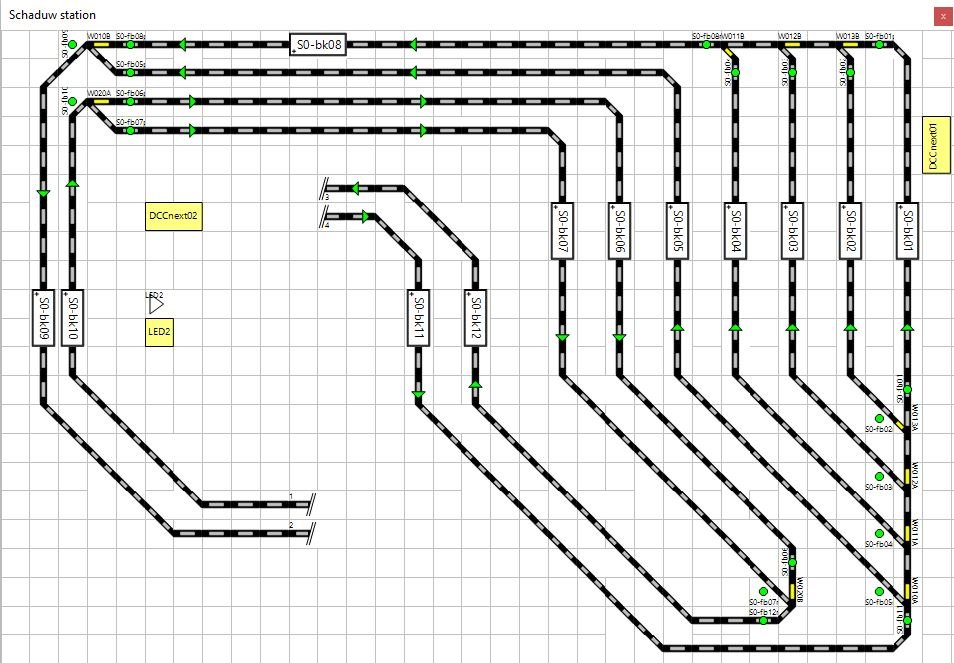
I managed to created a schematic layout of my shadowstation.
It has ten switches, which can be operated from Rocrail. Also my locomotives run smooth. In the loc decoder options I changed some setting. ONe of them is the maximum speed of the loco. The maximum speeds is now set to 60%. Which brings a much more realistic speed.
The track plan of the shadowstation in Rocrail. Looks much better then JMRI.
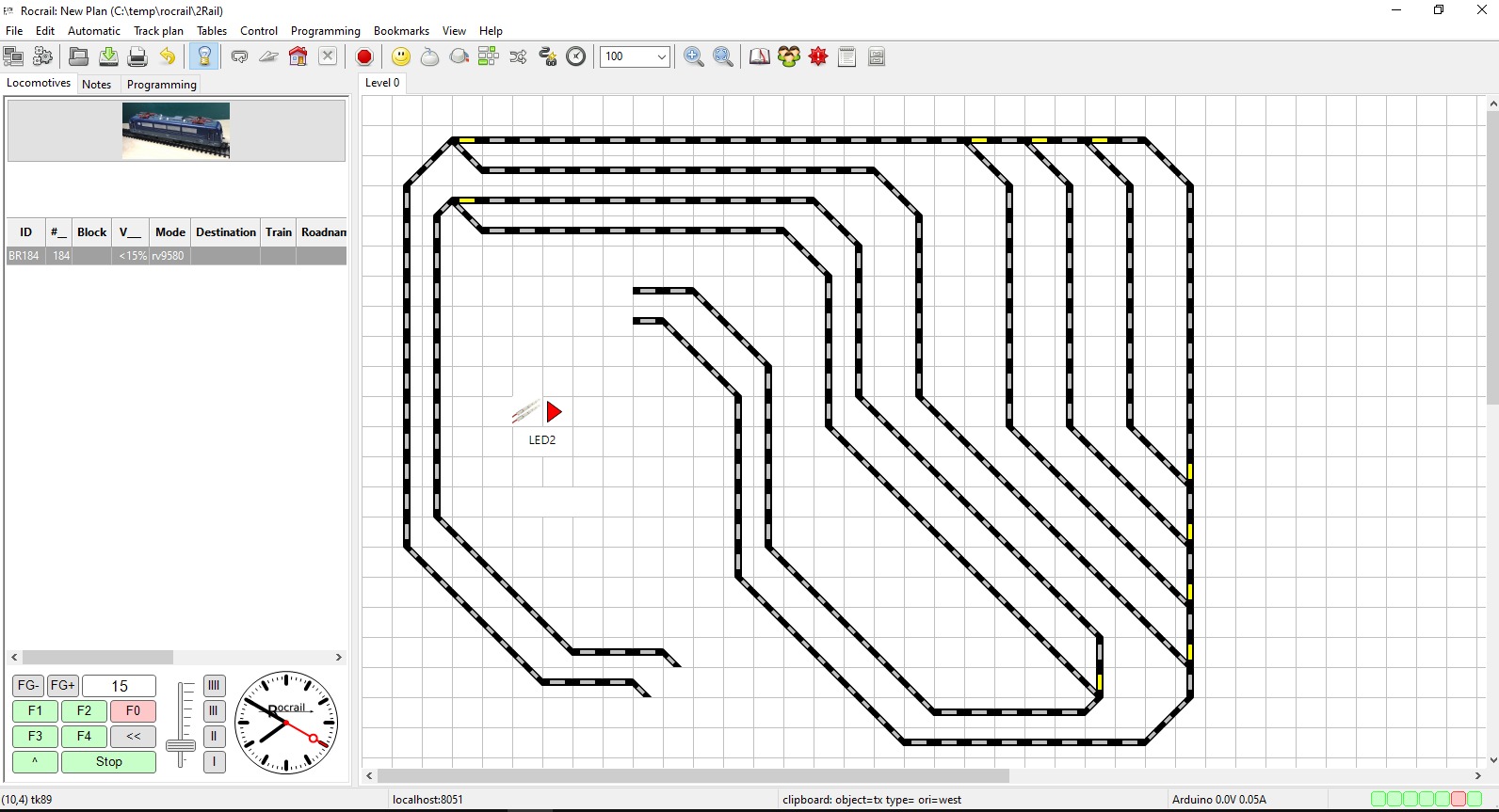
The "play" icon in the middle is to switch the LED strips on and off. Controlled by the DCCnext and MOSFET board.
The loco list is quite empty. Only one listed. It is about time I decide in which loco I build the decoders I have.
At the moment I have twelve decoders and many, many loco's.
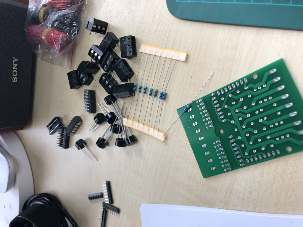
Next step will be defining the block and sensors. I will use current detection Arcomora's Arloco and OKKIE's.
Need to solder these together and configure them.
Next I need a Loconet to USB device. Currently I am investigating the possibilities.
The Arloco and Okkies are ready and configured. And work like a charm.
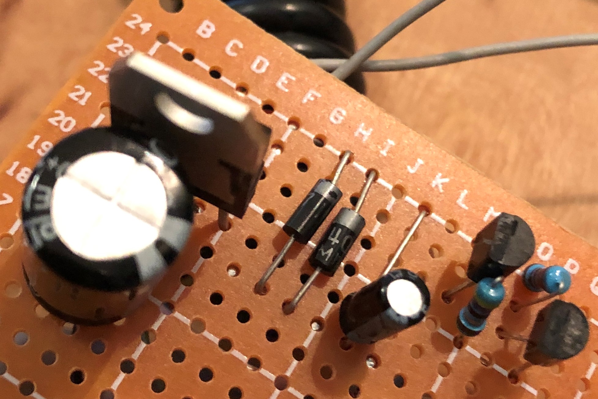
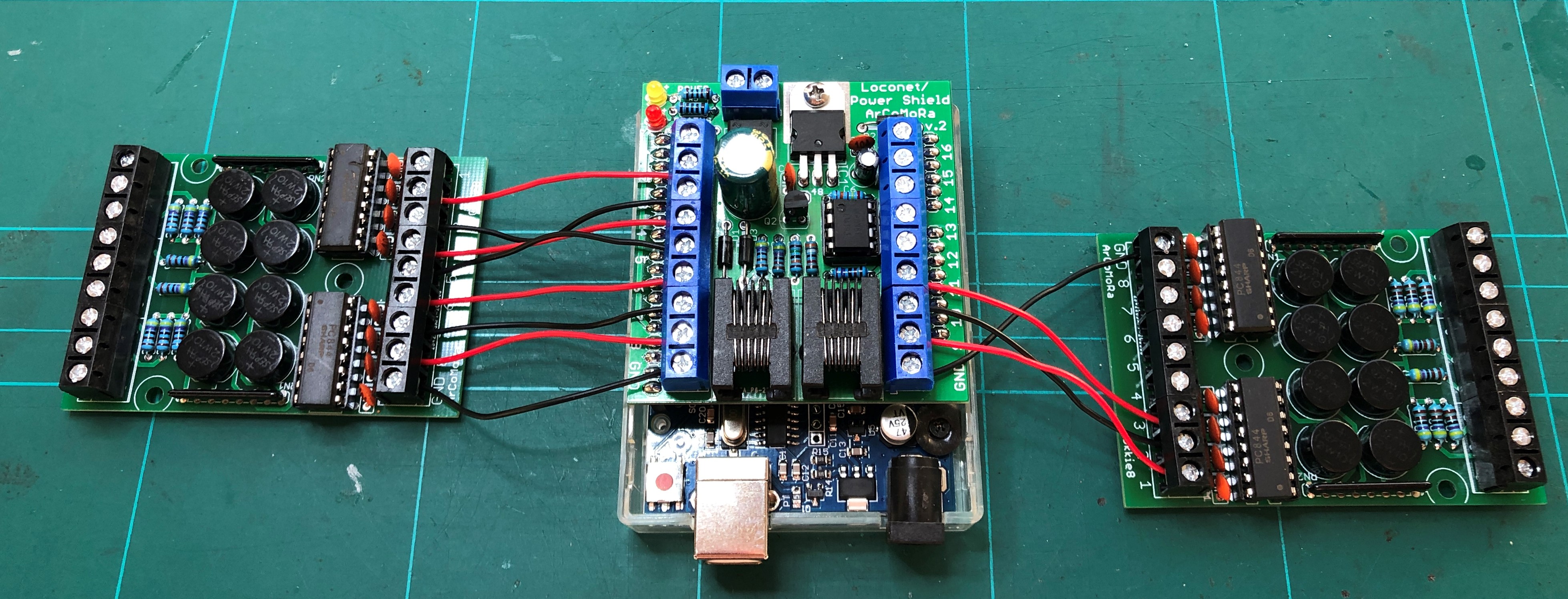
I use a Loconet to USB converter from Rosoft ( http://www.rosoft.info/LocoNet-Interface.html). At first I could not get it to work. After some reading I understood Loconet needs a current source and optional a 12 volt power power supply to feed the Loconet devices connected. So I found a schematic on the Internet and put te following together.
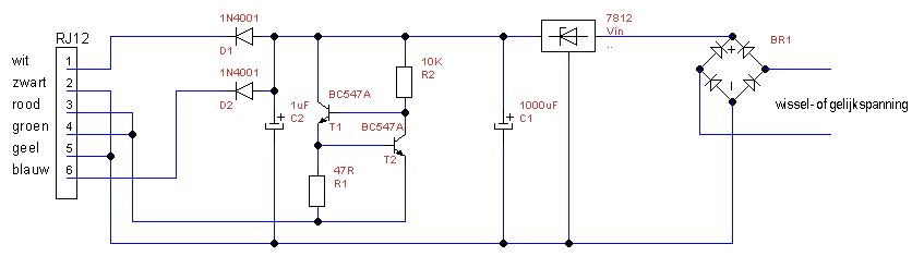
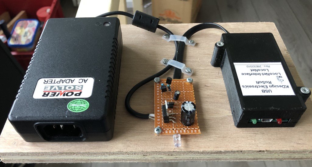
In real life it looks like this.
And it works. Happy me.
I cannot leave it like this and made it somewhat neater.
The last couple of weeks I was busy configuring Rocrail. Yes, decided to go for Rocrail. The more you use it, the more you get impressed by the possibilities. It has a steep learning curve though.
As mentioned before, the video's of Albert help me to understand how Rocrail works.
In the meantime I finished the schematic drawings in Rocrail for the shadow station and main tracks.
At the moment I can drive virtually my trains. This video gives you an impression.
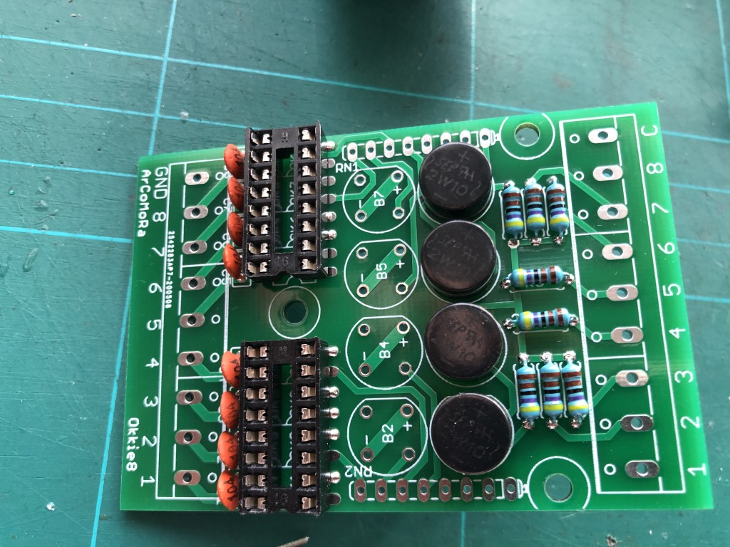
Now that is done, I could define the sensors that belongs to blocks. With an Arloco shield and Okkies.
The Arloco can handle fifteen current detection sensors via two Okkies. The Arloco can only handle 15 of the 16 ports on the Arloco shield, becuase of the design of the Arduino. Every Okkie has eight sensor inputs and eight logical outputs, which connect to the Arloco shield. See the manual on the Arcomora site: https://www.arcomora.com/download/.
Please note. You need to define an additional Controller in Rocrail (Rocrail properties - Controller - stop/start Rocrail) in the right COM poort.
OK, Arloco shield and Okkies are ready.
Previously I had per shadow track two blocks define. I simplified it a bit. It does not make sense to have two trains close to each other.
The shadow station now looks like this.
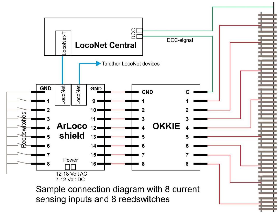
Here you can read more (in Dutch) about the diodebridge circuit; https://encyclopedie.beneluxspoor.net/index.php?title=Diodeschakeling.
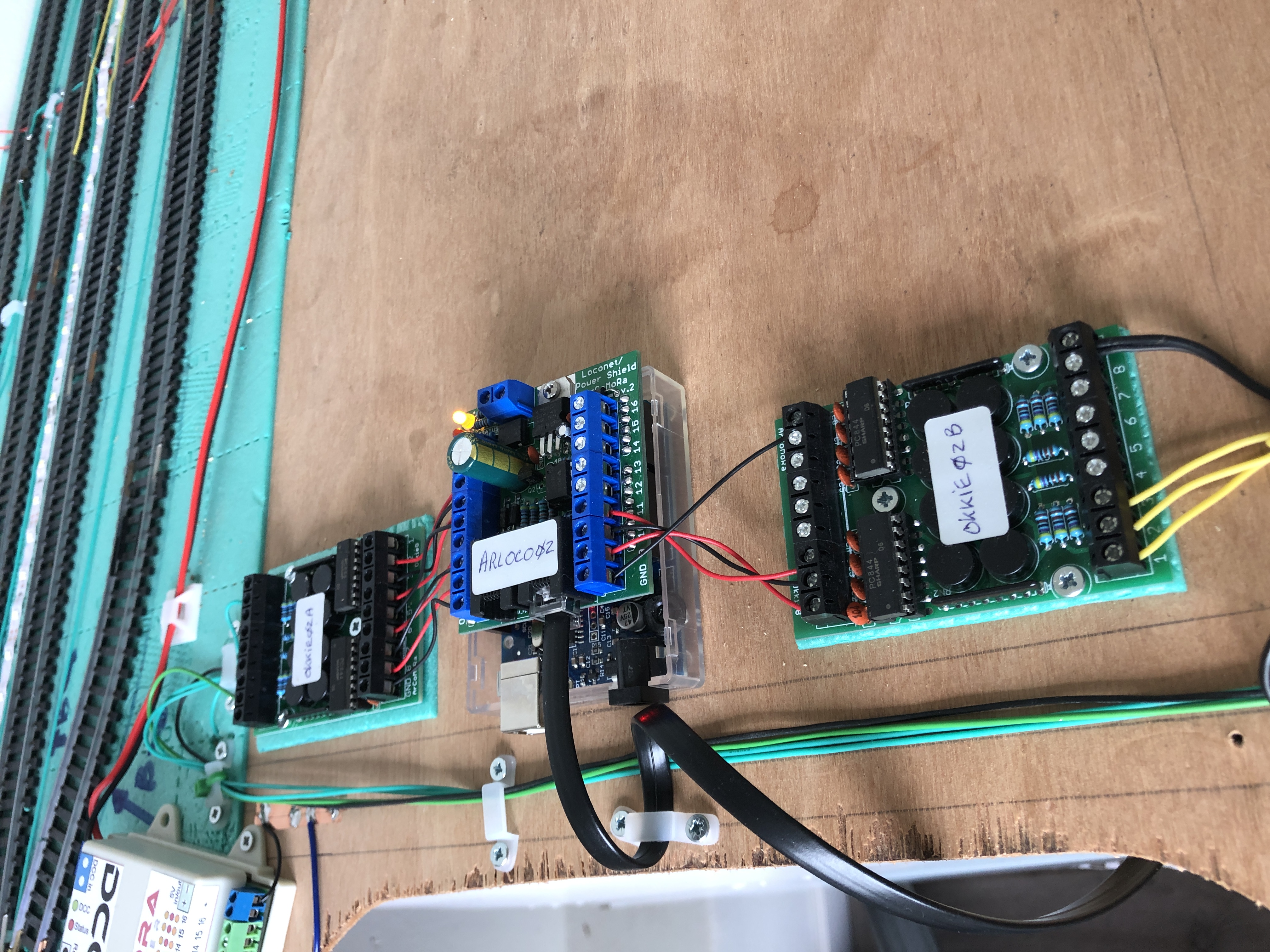
The Arduino with Arloco shield and an Okkie.
The green wires go to the pieces of tracks for current sensing. The flat cable coming from the Arloco shield is the Loconet connection.
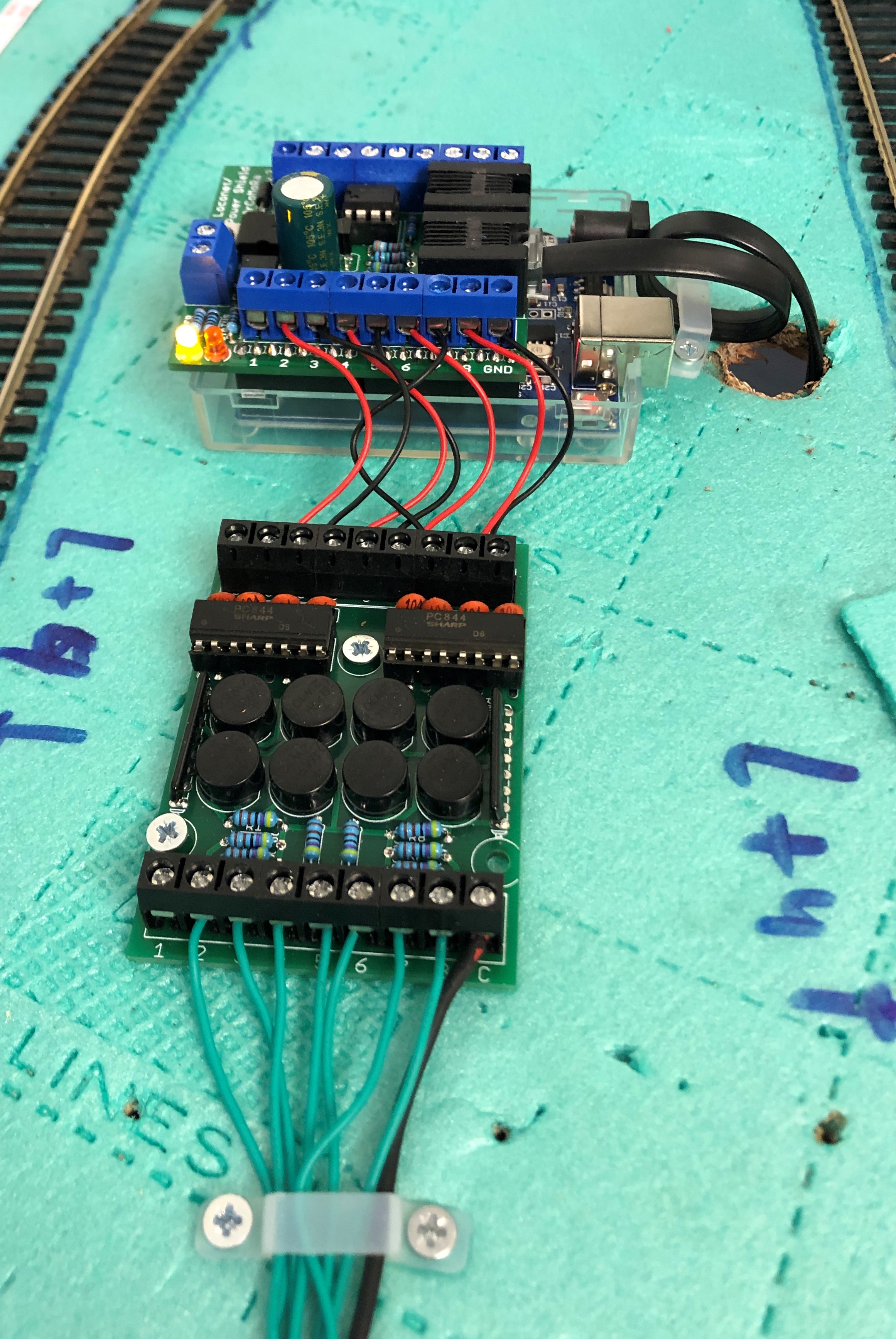
Soldered the second Okkie too. Maybe I can wire it the long New Weekend.
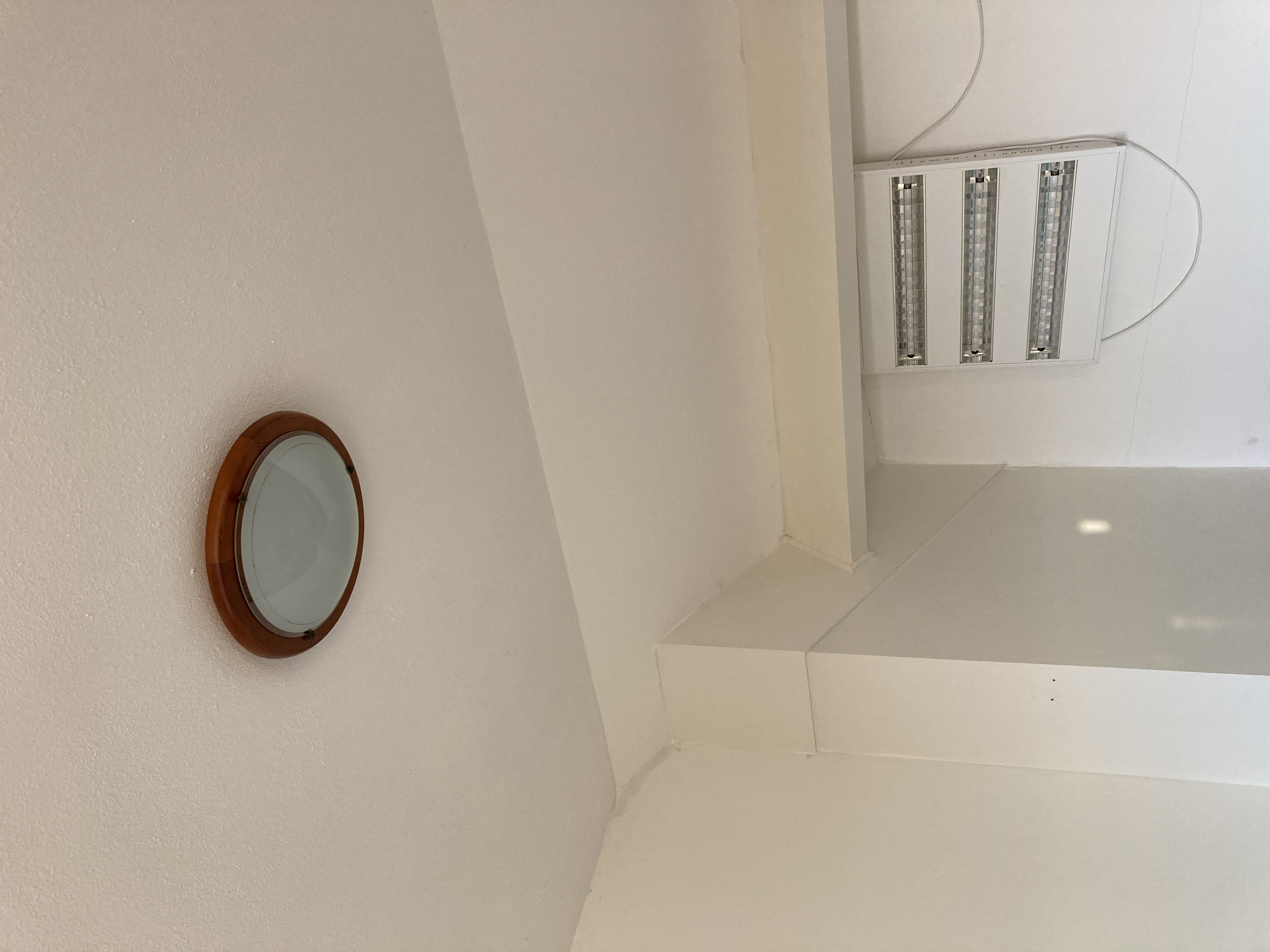
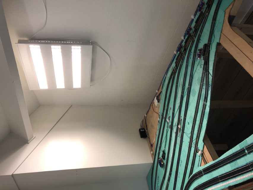
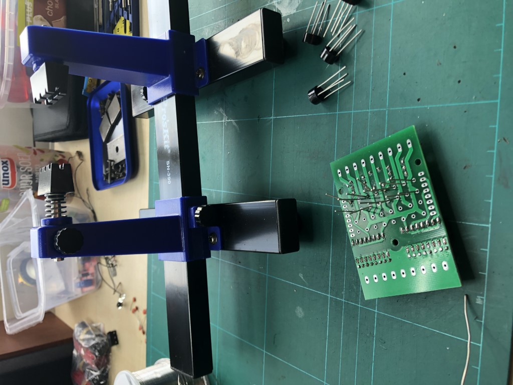
With the bad weather lately (and me getting older) I could not see enough while working on my model railway.
So, I knew I had a fixture somewhere in my shed. And found it, cleaned it, connected new wires and tested it.
Some hooks in the wall and voila, enough light to work in the darkest hours.
Hmm, already Januari 31st.
Somewhere I saw someone had bought or made a DC(C) tester.
And I thought I can make it myself for just a couple of Euro cent.
Here it is.
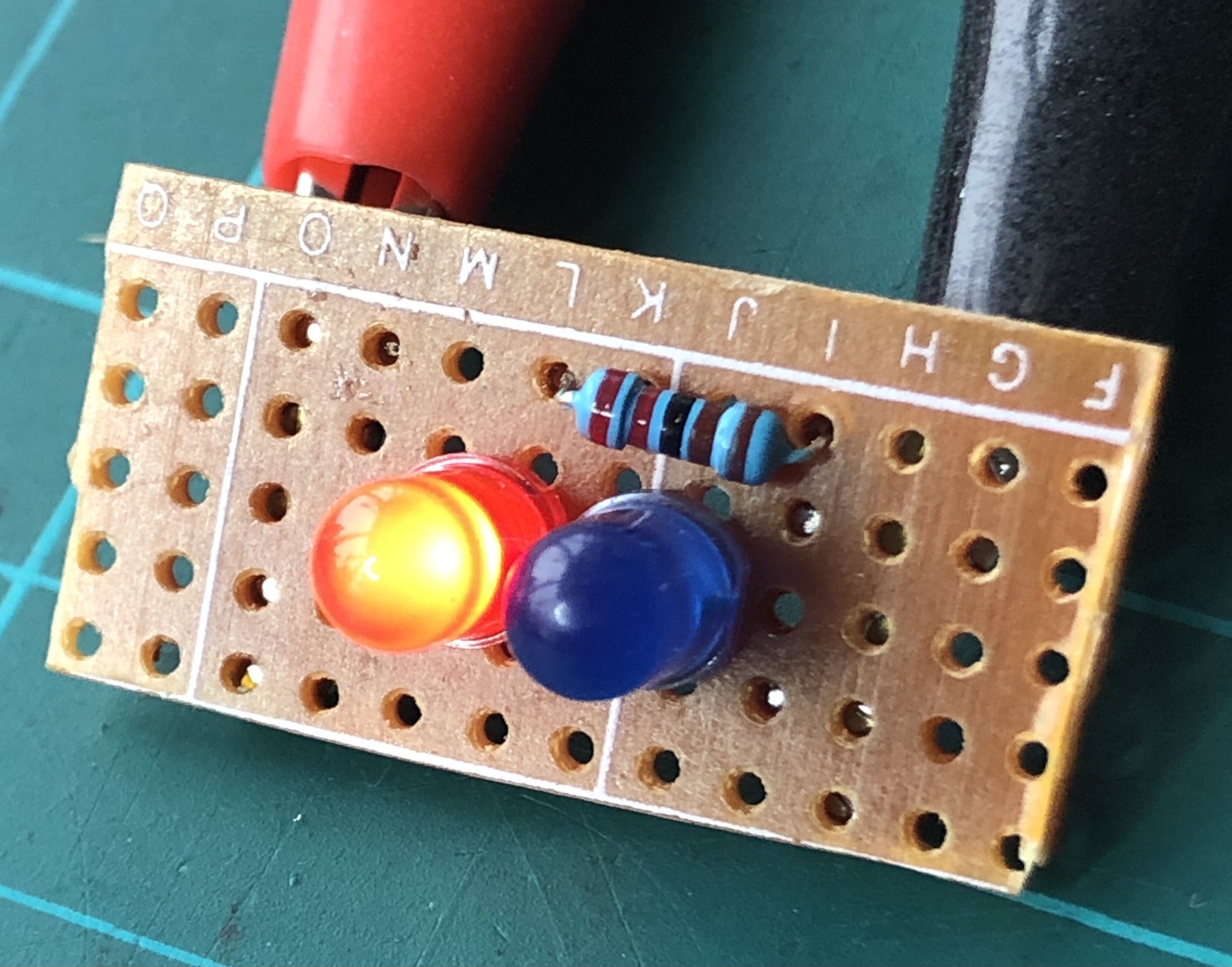
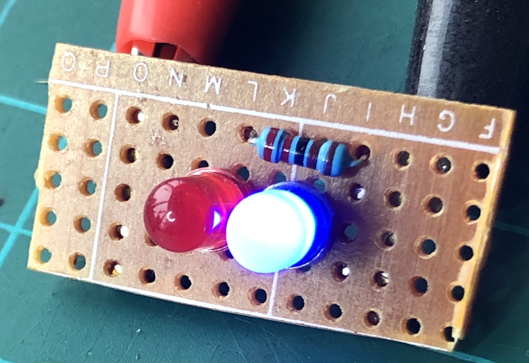
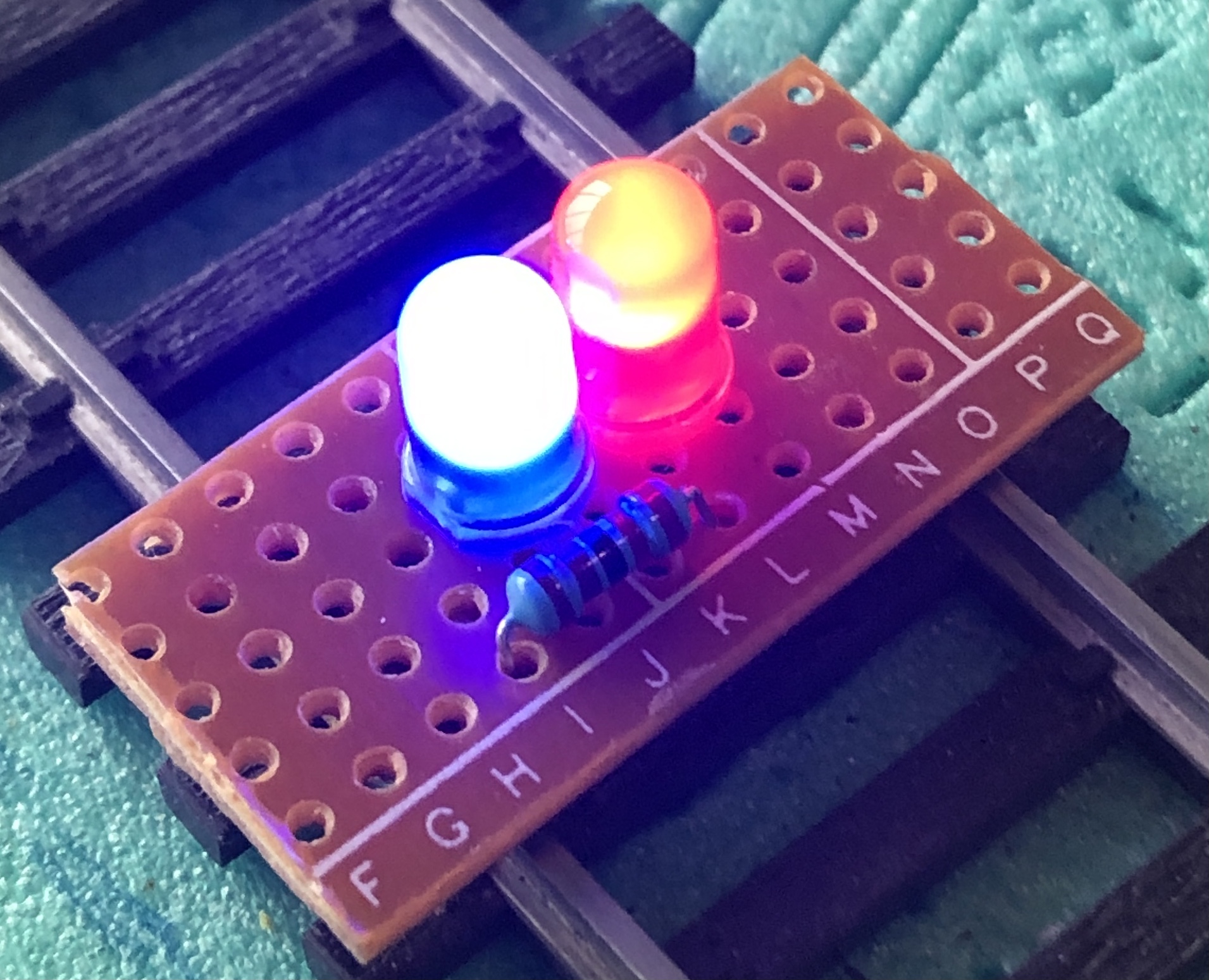
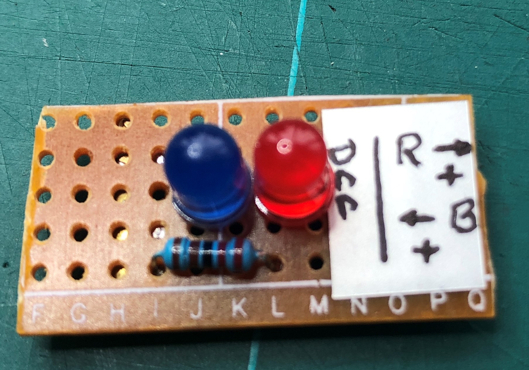
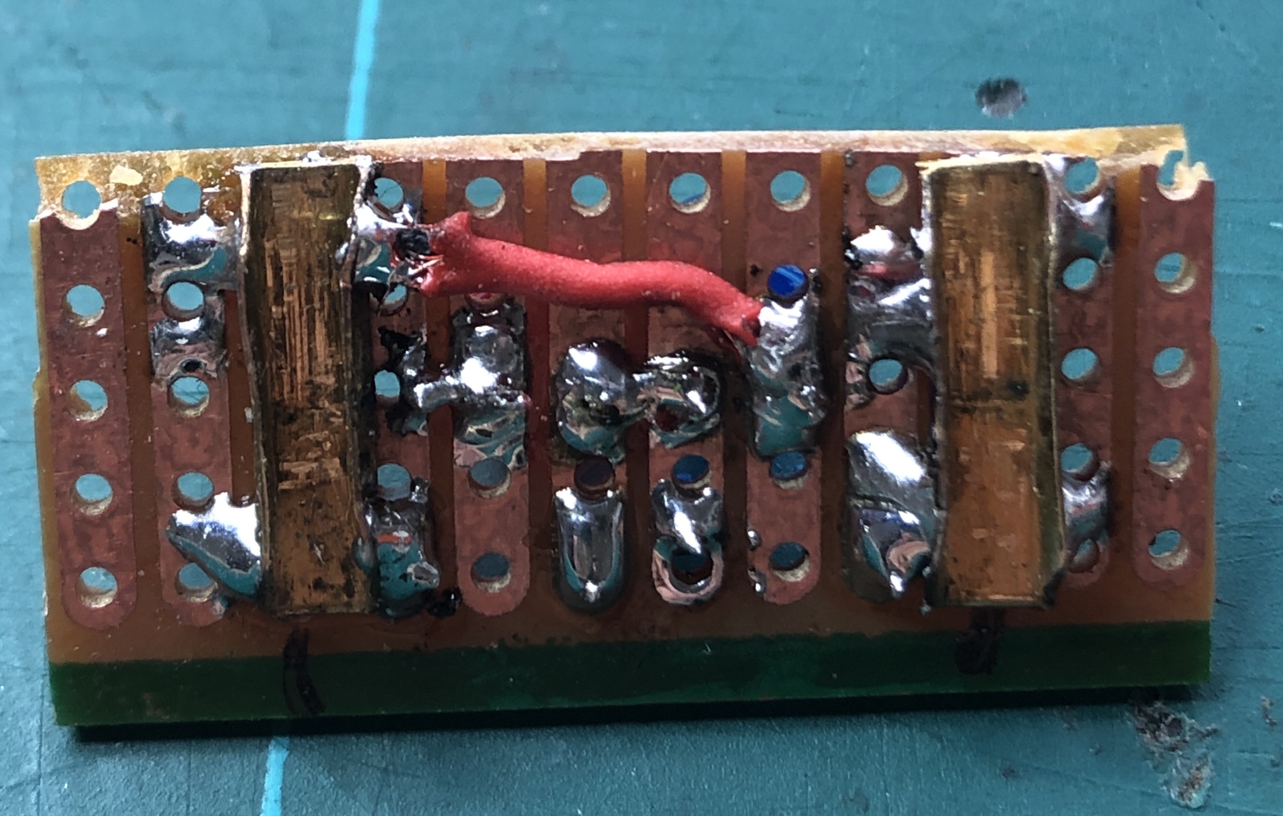
On a DC track, when the red LED lights up, plus on the red side.
It's not that I needed it, it is just because I can
Earlier I wrote about the Arloco and Okkies. Some of my blocks are not detected yet. I must finish that before I start with the main tracks. Time for some soldering.
The hardware is so affordable (Arduino/Arloco and Okkies) that I decided to use two seperate sets for the main track.
It helps me to keep my head clear.
Because I cannot remember everything I make notes about what I connect and to which. See sheet below.
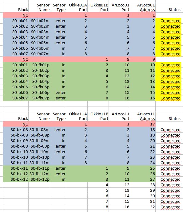
Guess what is next on my to do list.
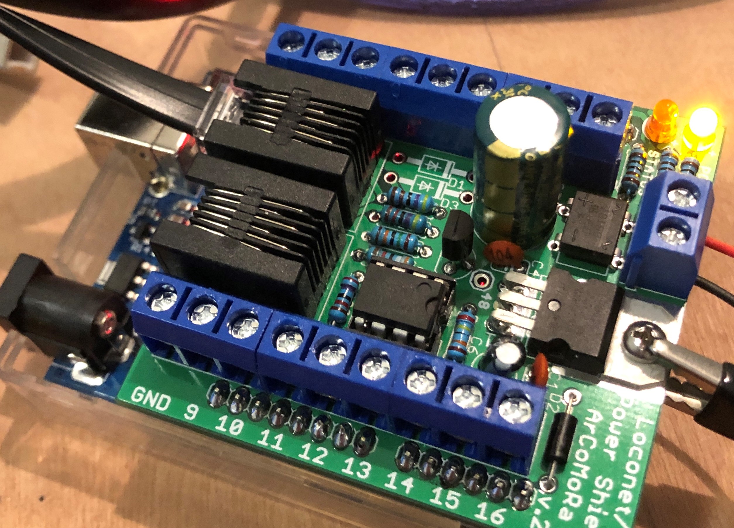
In the meantime I made plans to use a better, or more powerfull, H-bridge. The plan is to run ten trains at the same time. The current will exceed the 2 Amps the motorshield can deliver.
The new motorshield can handle 43 Amps, in theory. And my guess is I only need 5 Amps.
Because of a new video of Albert (what would I without him) about the successor of DCC++, DCC-ex, I was triggered to take a look at their site.
On their forum (and now on their pages too) discord.com I could find the properties of the IBT_2 board. Which already bought some time ago.
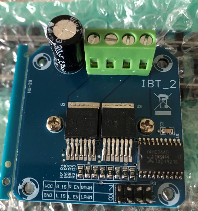
The plan is to use motor shield I am currently using on my workbench to program decoders for my locomotives.
So much to do, not enough time. Time to be a pensionado.
One of those ideas was to expand my shadow station. Or at least make preparations to make it possible.
On my artic I have some storage room behind the train table. Mostly stocked with stuff I think I will use (once) on my table.
And when I do there is space to add another three tracks to the shadow station. I know where the track will start. Do not know yet where it will come out of the closet
Maybe back on the shadow station or on the main track, I don't know yet.
In both cases the track will cross my walking space. The exit from the track is not a problem, as it exits near the wall.
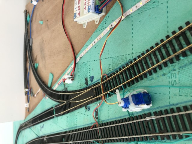
I just don't know where it will return from the storage space. Nevertheless, the switch is fixed and now the future will learn.
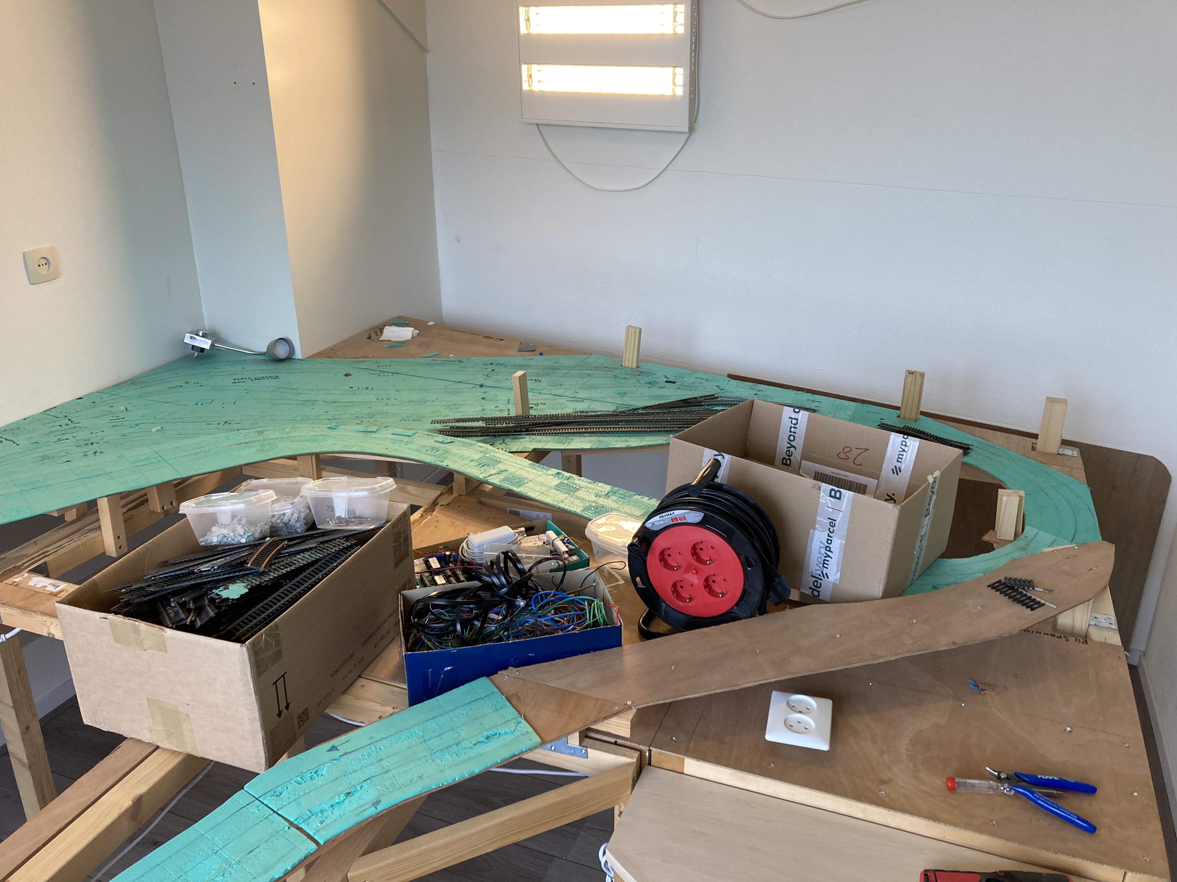
In practical it look like this. The pushpin are to fix the rails for now, as I just glued them down. Will be removed later when the glue is set.
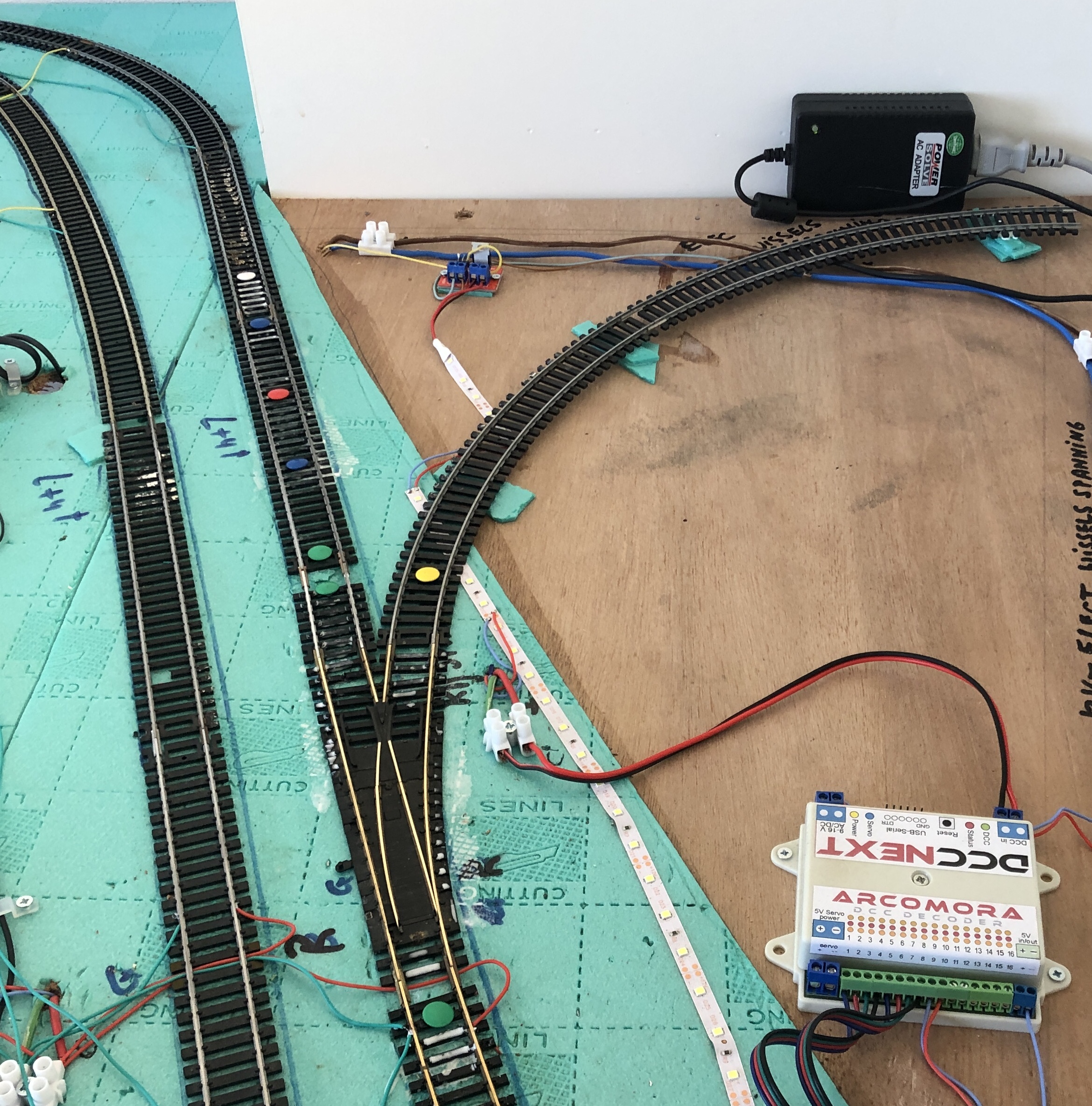
Added a servo to control the switch. Now the main level hasn't been build yet, I can easily access it location.
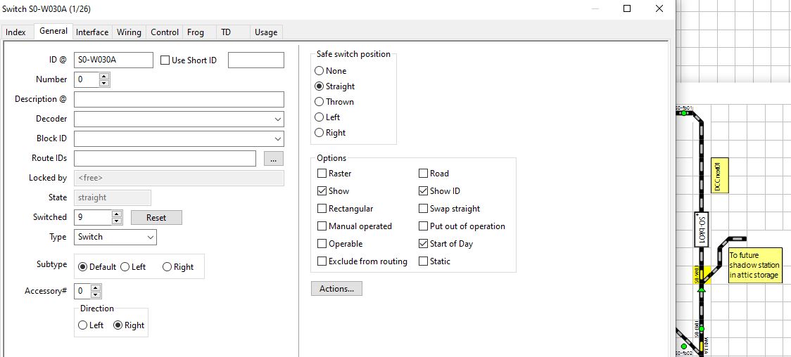
Configured the switch in DCCnext 01 and in Rocrail, with corresponding DCC addresses.
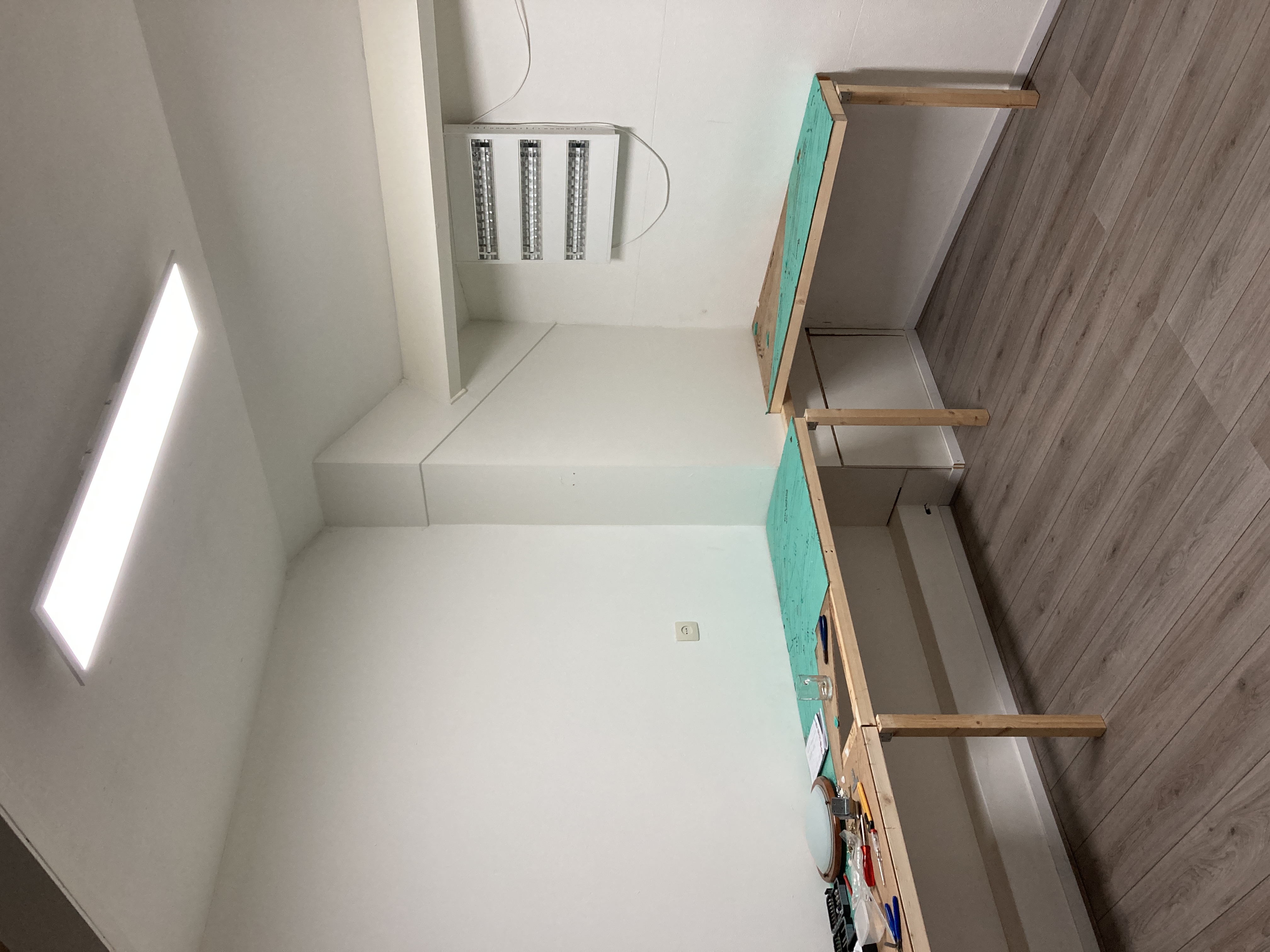
I had to make room for some maintenance that has to be done at my house.
Cleaned out the cabinet with all rolling stock and documented them in and Excel sheet with details of the rolling stock. And took pictures of all pieces.
You are probably like me, and have too much stuff.
All my Dutch train material is now displayed in a small cabinet in my living room The rest is put in boxes.
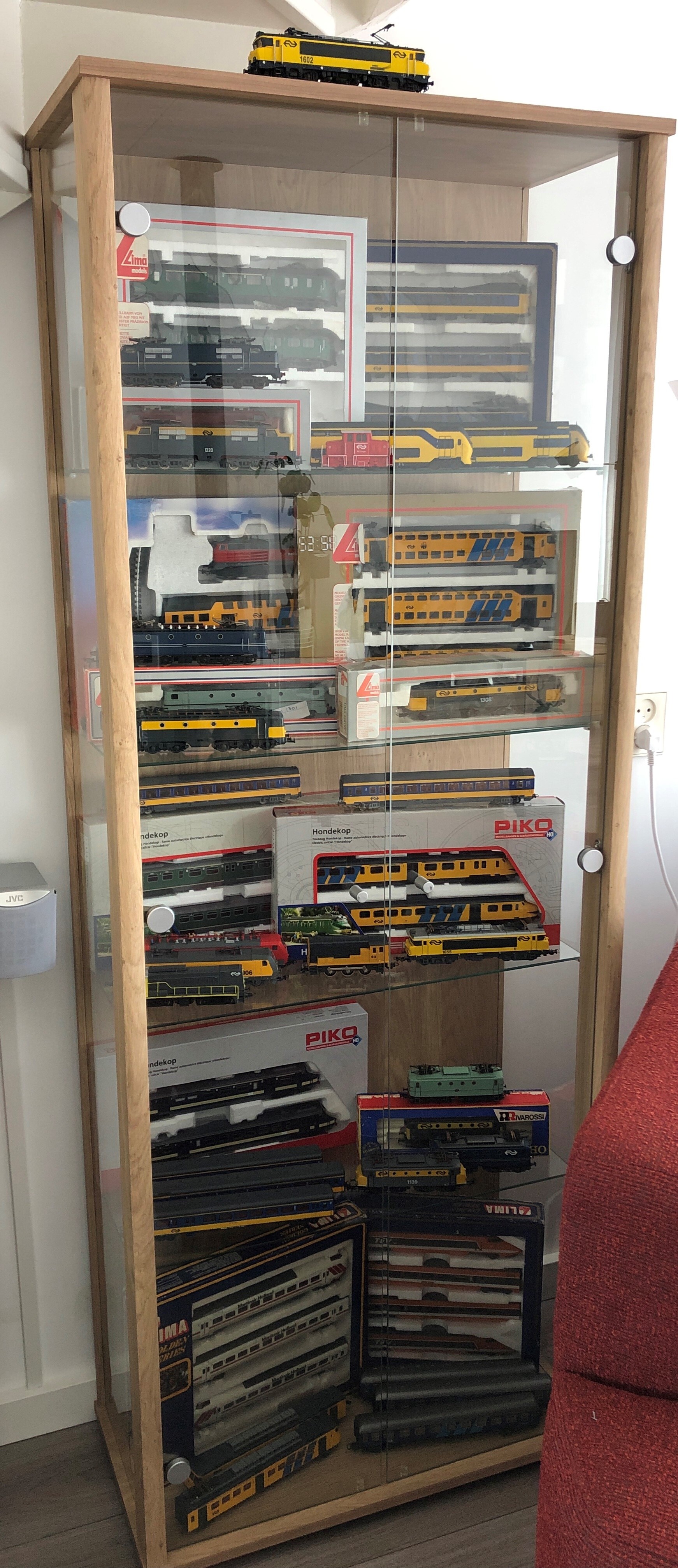
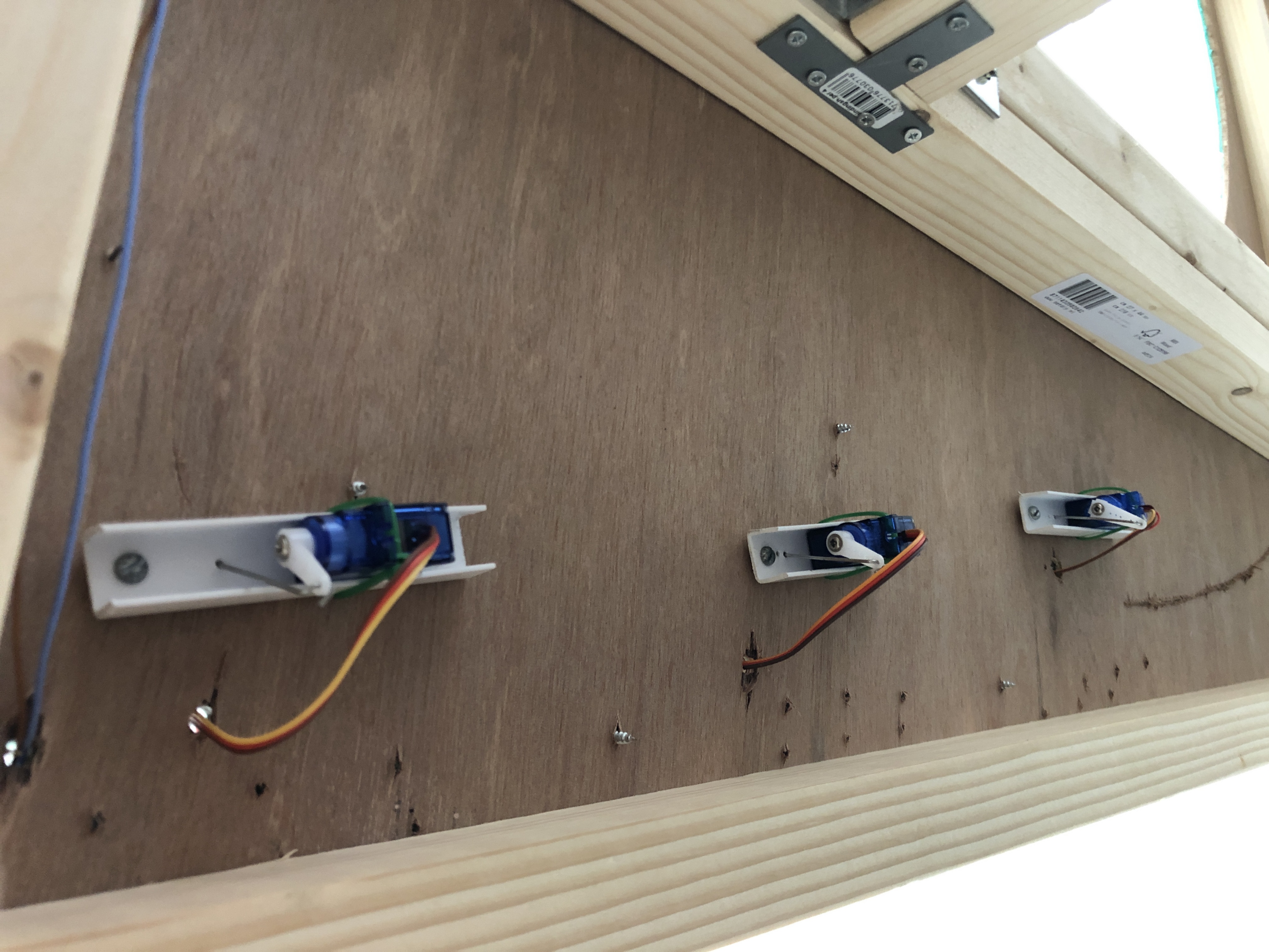
Some mounted on top of the table. Simply becuase there was nog space under the table.
Top mounted servo's

Hopefully I find the time and energy to start agian.
Possibly I will start all over again. Because of new insights and plans.
I have made another track plan. It assumes that the fountain will be removed.
The pipes and drain pipe have been neatly capped. That was step one.
A good friend had already suggested removing the chimney (conversion). I only use the fireplace as decoration.
I hesitated about it for a long time. You have to approach something like that carefully. You don't want the pipe to fall down or the pipe to come down through the roof.
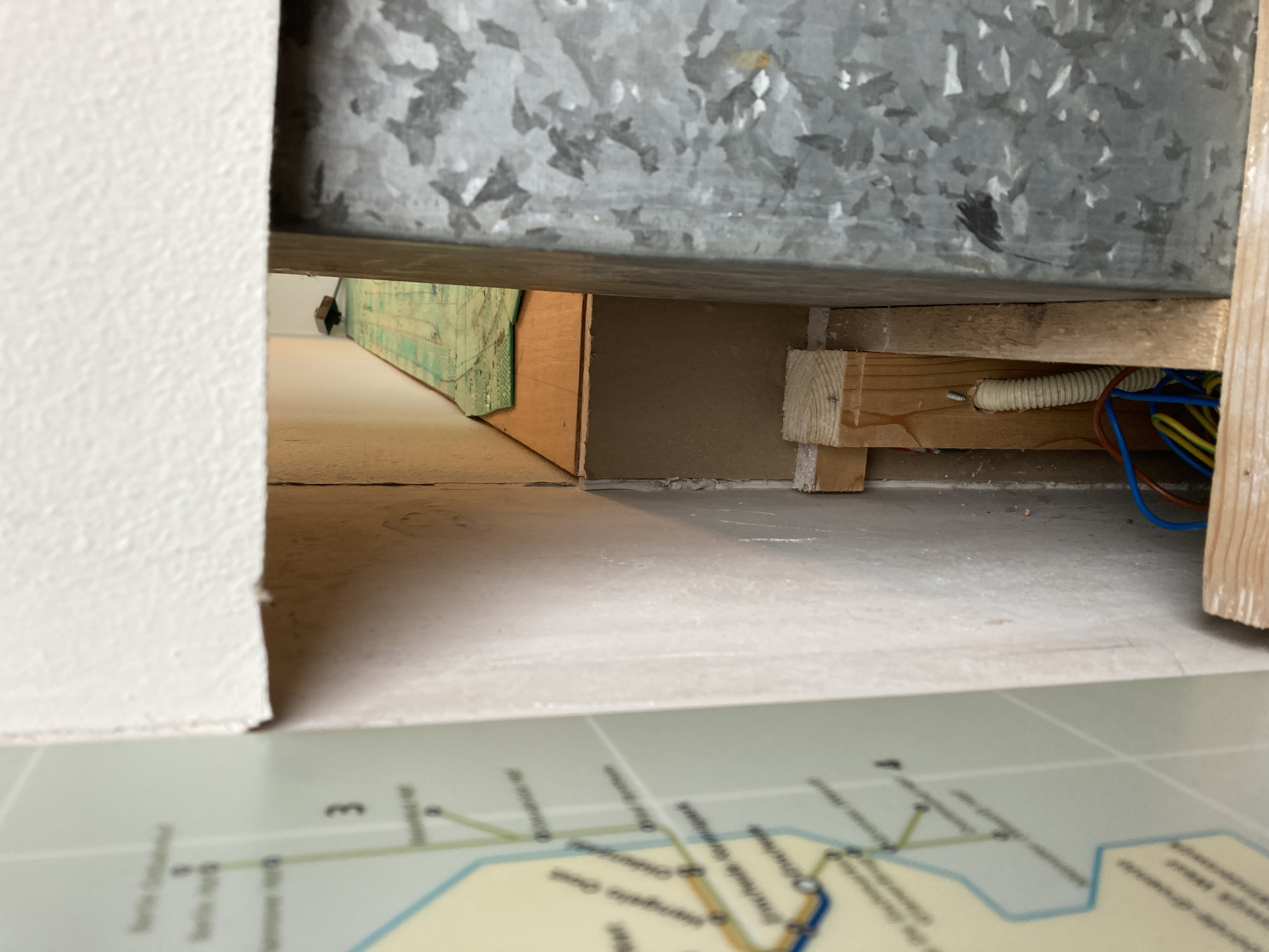
This week my friend helped me make progress. We removed a piece of the plaster casing of the chimney. Unfortunately, there was a steel casing around the pipe. So removing the cove was not an option.
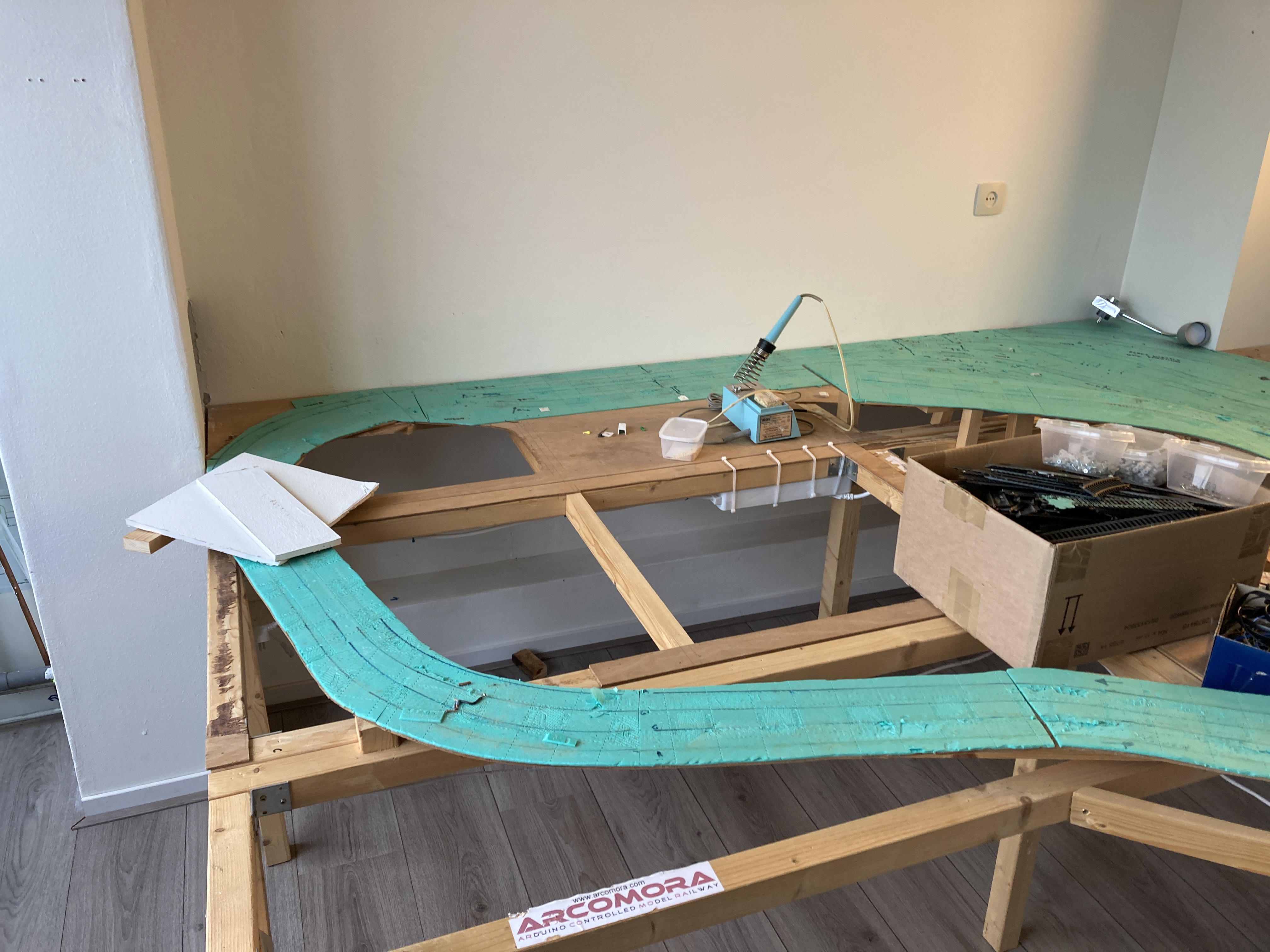
Nevertheless, we achieved a success. It turns out that two tracks can be led behind the pipe. See photo.
Because I had made a different plan, where I can reach the tracks better and do not have to crawl under the table (not nice with a bad back), the current plan also has to be removed.
We did that the same afternoon. Of course, we also had to remove all the wiring. See both photos.
Below is the track plan that I made a month ago. It still has to be changed, because the tracks have to go behind the chimney.
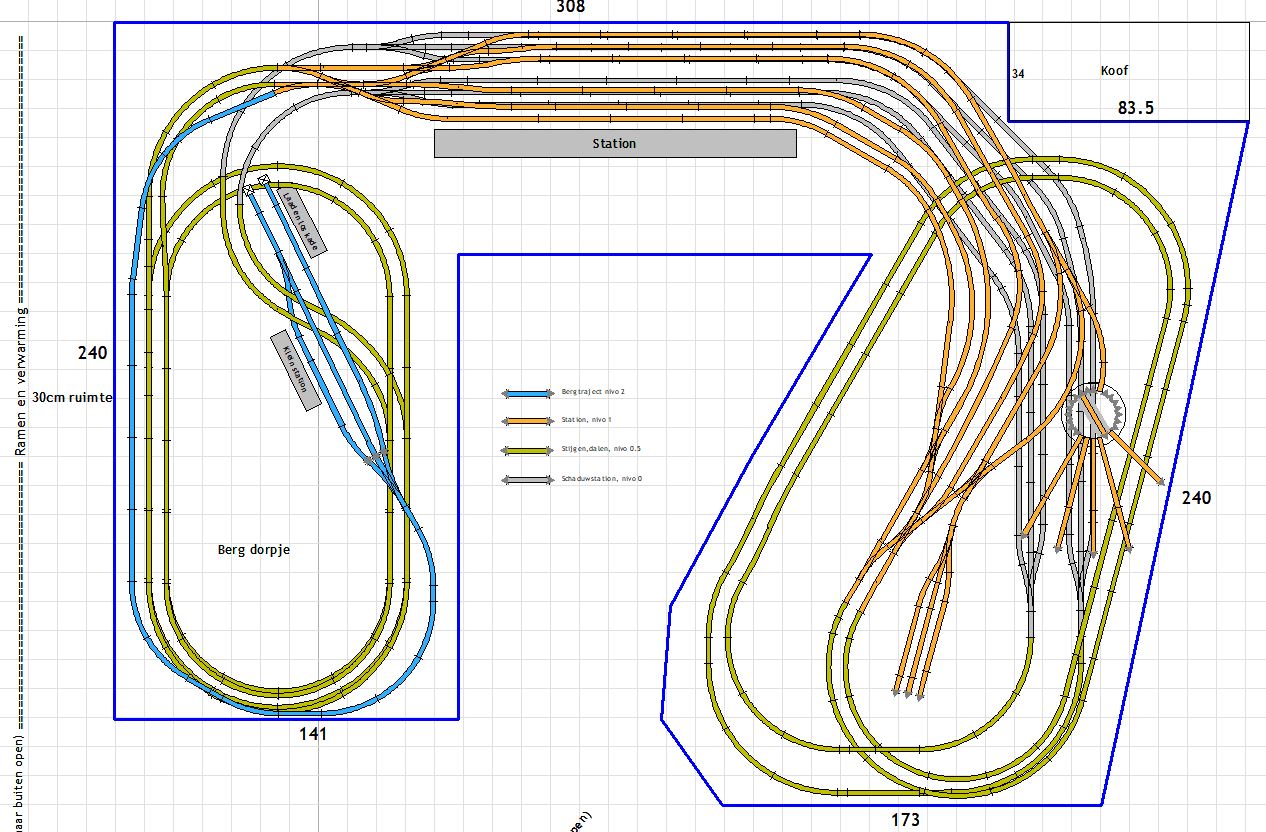
Click on image for a bigger picture.
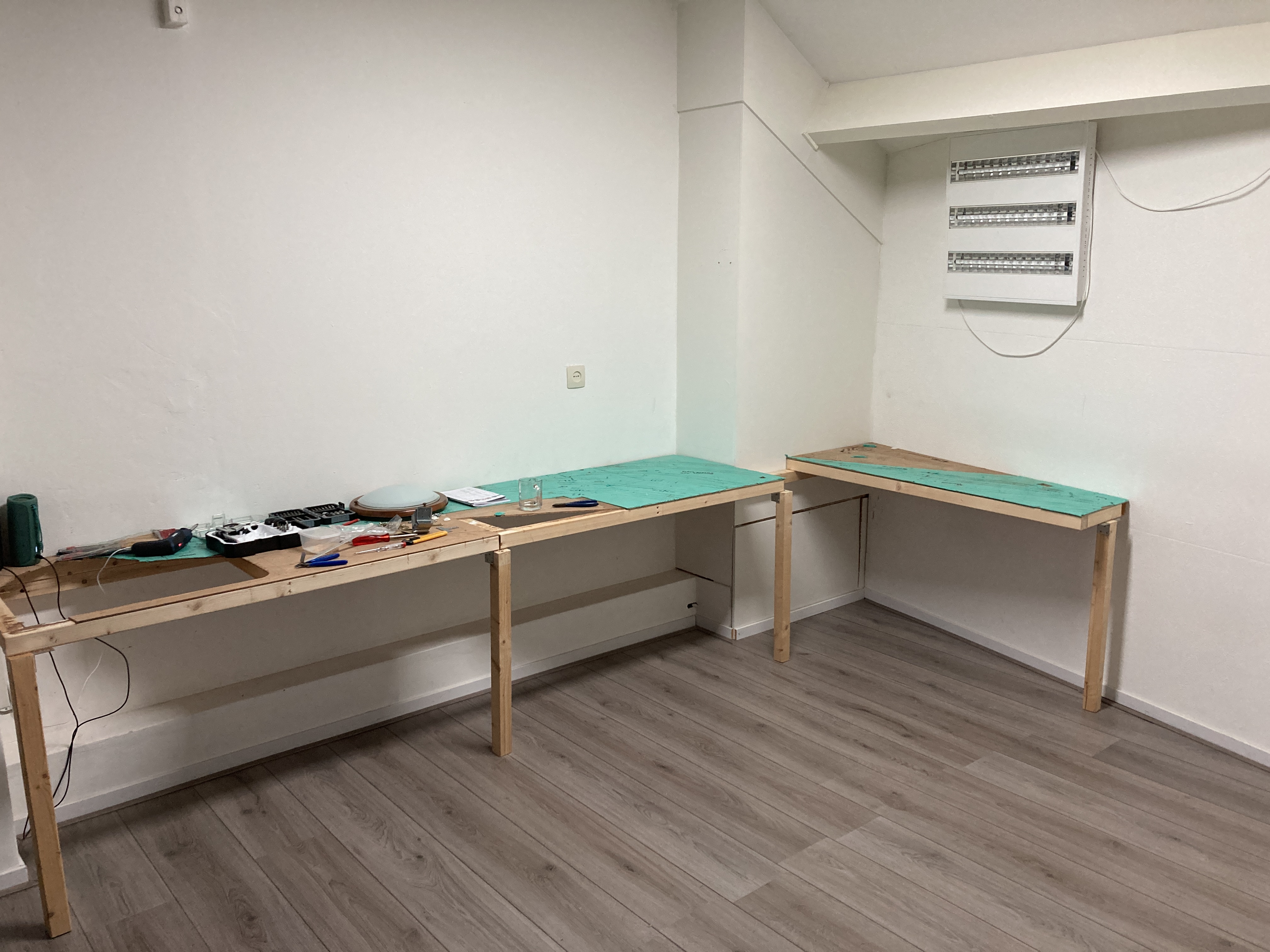
For the new track plan, most of the wooden frames have to be taken apart and reattached in a different way.
The new track plan is almost ready and I will show it here when it is. It does not differ much from the plan that was shown above. Had to rebuild everything to be able to go behind the chimney.
If I have measured everything correctly, this should work.
There are only two modules in the same place at the moment.
Dat is ook gebeurd. De lamp is met afstandbediening in te stellen met kleurtemperatuur en licht sterkte.
Oude situatie.